 Menu
Menu


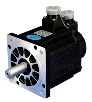
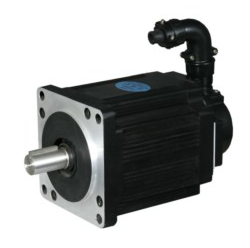
DCYJ-08
-
Min Order
1
-
Product Unit
Pieces
-
Origin
China Mainland
-
Payment


- Contact Now Start Order
- Favorites Share
- Description
Product Detail
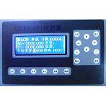
Product Model:DCYJ-08
The core of the controller is embedded computer. It is Chinese LCD human-computer interface and featured with simple operation and high flexibility. All operations are done by the Chinese program setting that it can fill out the reminding form of the controller to complete the program without any commands. It is equal to a PLC add a screen integration. However, compared with PLC, it is much easier that even a common operator can operate it. Besides, it is interrupted resistance, which can work stably even under the welding condition.
Main performance
1. Control 1 stepper motor or servo motor, rotate speed and angle can beset as you required.
2. Positive and negative protection for the motor
3. Return to coordinate zero
4. Return to mechanic zero
5. Zero position remind
6. Counter automatically and it can set the quantity for the process workpiece
7. Circulated process, and the circle times can be set
8. 10 individual output ports, and No.1 and 2 output port is interlocked
9. 20 individual input ports
The specification of the controller is as below:
1. Input power supply:DC24V,DC5V
2. Control accuracy:1 step
3. Environment temperature:—10~+40?
4. Relative Humidity :80%(25?)
5. Size:188*120*34(Width*Height*Thick)mm
6. Weight:1kg
??Performance of Key
(?)Controller panel and keys

Press‘?’or‘?’key, It means to move to left or right.
Press‘?’or‘?’to display the previous or next page.
Press +’or‘-’:The parameter in the cursor will be plus or minus1 after press it.
The counter will be 0 when press the clear key.
The controller will be at original display when press re-set key.
Press clockwise or anti-clockwise rotate key, the motor will rotate clockwisely or anti-clockwisely, and it will stop when the loose the key.
It will process automatically when press start key, it will switch to processing way of continuous, single process or single time if it is not during the automatic running. It will stop temporarily when press stop key under automatic condition, and re-press the stop key, it will switch to processing way of continuous, single process or single.
(?)Outside connecting keys
1?The controller provide the outside connecting keys below:
It will process automatically when presses the start key and it will stop temporarily when press stop key, then press the start key, it will go on with the process. If you want to esc, press the re-set key. The outside connected start and stop key is same as above, and it is series connected.
The motor will return to 0 position when press the return to zero (outside connection) key.
Press return to mechanic original point key, the motor will anti-clockwise up to mechanic original point switch or negative limit switch with manual speed, and then clockwise rotate out of the switch and clear the position.
Note1: the definition of single process, single time and continuous
Single process: It will temporarily stop when process one page, it needs to press start key to implement next page.
Single time: It will temporarily stop when finish the whole processing procedure, it needs to press start key to implement next whole procedure.
Continuous: It will process continuously until the required quantity is finished or it will stop when you press stop key.
Note2: There are two kinds for returning to the mechanical zero
(1)The motor is not out of signal switch of the mechanical original point when press the “return to mechanic zero'' key, the drawing is as below
a?It is effective that the motor anti-clockwise rotate to mechanic zero signal by manual speed.
b?It is ineffective that the motor anti-clockwise rotate 20 steps, the mechanic original point signal should be effective at this time.
c?It is ineffective that the motor clockwise rotate the mechanic signal slowly
(2)The motor will be exceed the mechanic signal switch when press the key of return to mechanic

a?It is effective that the motor anti-clockwise rotate to negative limit switch by manual speed.
b?It is effective that the motor clockwise rotate to the mechanic signal slowly.
c?It is ineffective that the motor clockwise rotate to the mechanic original signal slowly.
2?The controller has the ports for outside input/output signal
Receive 1: It will continue to process when the waiting signal is low.
Receive 2: It will continue to process when the waiting signal is low.
Receive 3: It will continue to process when the waiting signal is low.
Receive 4: It will continue to process when the waiting signal is low.
Receive 5: It will continue to process when the waiting signal is low.
Positive limit: The motor will stop when the signal is low during the motor running clockwisely, the controller display positive limit and waiting, press re-set key.
Negative limit: The motor will stop when the signal is low during the motor rotate anti-clockwise. The controller display positive limit and waiting, press re-set key.
Mechanic zero position: It is used to return mechanic zero.
Note:
1?All keys, receive, limit switch and mechanic zero signal adopt normal touch point without interlock function, and it can be effective under lower power level.
2?the difference between return to zero and return to mechanical original point:
Return to zero means the motor return to the position of “0'', the distance and the direction that the motor run is related to the position that the controller set.
For example, if the controller position is set as +0526.780, press the “return to zero'' key, the motor will run anti-clockwise up to 526.780, and then stop, and if the controller position is set at -0132.255, press the press the “return to zero'' key, the motor will run clockwise up to 132.255 and then stop.
Return to mechanic zero means the motor returns to mechanical original position of signal switch, the distance and the direction that the motor run is related to the position of mechanic original position of switch signal but is not related to the position that controller indicated.
??LCD Parameter Setting
Press‘?’?‘?’?‘?’or‘?’to move it and press +’or‘-’ to plus or minus the display, or exchange between the on and off.
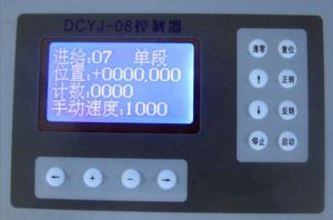
Initial Pag:

Feeding step: It means the processing is on which step, 00 means it is not on processing while 01, 02…. means the processing is on 1st, second, third…. step.
Continue: It means it is at continuous processing condition. It may indicate stop temporarily, single step, single time and continue when press stop key.
Position: It indicates the motor position, presses re-set and edit keys at same time, the loose edit key after loose the re-set key, it will clear all data, the unit is mm or degree.
Counter: The already processed quantity, press rest and stop key at same time, and then loose the stop key after loose the re-set key, it will clear.
Manual speed: Press clockwise rotate, anti-clockwise, return to zero and return to mechanic zero key to set the speed, unit is mm/minute, the outside connected rotate is same.
Feeding Page
here are 25 pages for the controller that can set 25 processing steps, all parameter setting method and operation is totally same. Presses the start key to start the processing from the page 01 to page 25, we take page 01 as example to introduce the setting and implement.

01 step: “on'', it will implement the page automatically while “off'', it will not implement the page under automatic running, the setting of prolong, speed, distance, send signal and receive will not work.
e.g. “On'', it will implement the page under automatic processing
Prolong:the waiting time after implementing the signal sending, receiving and motor running;unit:Second
The example is 0.2, it means prolong 0.2 second?
Speed:It means the speed of the motor, it the data is 0; it means the motor will run with the speed last time.
The example is 3257; it means the motor is running with the speed of3257mm/minute
Distance: The moving distance of the motor, if the length is positive, the motor will rotate clockwisely while if it is negative, it will rotate anti-clockwisely. If it is 0, the motor won’t rotate.
The example, +0032.328 means the motor rotate to 32.328 mm
Receive signal: It can be set as you required from 0 to 6, check the receive port of 1 or 2?3?4?5?6, 0 means not to check the receiving signal. When it is on it means the signal sending port is on while off means the port is off. If it is “'' means that the port has no any change.
In the example, the receive 2 is on, it means the signal sending port is on.
Note:
1?Signal sending 1 and 2 is on interlocked, it means when the signal sending 1 is on, the 2 is off, and if the 2 is on, the 1 will be off, but if the signal sending 1 is off, the 2 will not change and signal sending 2 is off, the signal 1 will not change. The signal 1 and 2 is used to control the rotate direction of the main shaft.
2?When the signal sending is on, the signal foot will send low power level (100mA drive) to another controller grounding foot of DC24V relay.
3?The signal sending foot is DC24V open circuit output.
Receive signal: It can set 1~8 as you required, and check the port 1 or 2?3?4?5?6?7?8 while 6, 7 and 8 is used to limit the length, when finish the distance, to check the power level signal of 6, 7 and 8, if it is low, the motor will stop.
When it is on, it will go on to process when the checked port is under low power level otherwise it will wait, and the motor won’t rotate.
When it is off, what ever the power level of checked receive signal port is on or off, it will go on to process.
In the example, the 4 is on, if the receive signal 4 is low power level, it will go on to process otherwise it will wait until the signal 4 is low power.
Note:
1?The signal receive port requirement:
a. Low power level or grounding short circuit with 24 V, the power level should be less than 1.0V;
b. The power level should be more than 10V or the foot suspended if the signal is ineffective;
c. The last time of the signal should be more than 15ms (0.015 second)
2?There are many ways to produce the signal in the signal receive port:
a. It can adopt touch switch similar as travel switch, the 2 feet of the touch switch connect with the signal receive foot of signal receive and 24V grounding foot of controller.
b. It can also adopt DC24V approximate switch or its power supply controller, +24V, its grounding controller, 24V, and its signal receive foot. The common ones can be used in the market are from DC8 to 36V.
The implement order of each page is as below:
(1) Send signal (2) receive signal (3) motor move (4) prolong
when press the start key, the implement is as below:
Step 1: To make the signal sending 2 as “on'' condition whether the 1 is on or off, and make the signal sending 1 at off condition.
Step 2: Wait receive signal 4 until the low power level
Step 3:The clockwise rotate the motor move to 32.358 mm with the speed of 3257 mm/minute
Step 4: Prolong to wait 0.2 second;
It will implement the page from page 2 to page 25 after the page is implemented. If the page feeding page is off, it will flick to another one. If the circulated processing is on, it will circulate from the setting page until finished the circulated times you set. Other 24 parameter setting and processing is same as the example.

The implement order of example 2
Step 1:To make the signal sending 3 at off;
Step 2:It will implement the next step as the signal receive is off;
Step 3:The motor anti-clockwise 1021.200mm with the speed of 500mm/m;
Step: It will implement the next page as the prolong time is 0.

The feeding 09 page will be implemented as below:
As the page is off, the controller will flick the page to another feeding page.
Zero position and cycle page:

Zero position remind:
On: The position value will not be 0 when press the start key, the position value will flash to remind you, if you do not want to start at 0 position, press the start key again otherwise to esc with pressing the re-set key.
Off: It will start immediately when presses the start key even it is not at the 0 position.
Circulated process:
“On'': Press “start'' key to start the processing from the page 01 until the setting ending (the example is set at 12 step), and then it will return to the beginning (the example is set at 03 step) until finish the setting cycles (example is set 1236 times), and then implement it until the last page.
“Off'': The cycle process will be turn off, and the setting cycles will not work. If the cycle process is off in the example, when finish the 12 step processing, it will go on to the next page 13 but it will not return to the 03 step.
Cycle times: It means the times that the processing repeat.
Cycle beginning: The initial cycling page
Note: The beginning of the cycle can not be 00, and the ending of the cycle should be within 25, and the beginning should be smaller than the ending.
Motor parameter page:

Distance of motor step: It means the moving distance of one step that the motor rotates, in other word, it is electric gear ratio, unit: mm/step
The data is related to transmission data, motor step angle, motor drive sifting or servo motor resolution.
Example 1: 130BC3100A motor will move 4mm per rotate, stepper motor will go 0.6 degree per step and one rotate needs 600 steps, the step distance of the motor at this time is 4.000/600=0.020/003
Example 2: The speed of 110BYG2501 stepper motor is reduced as the ratio of 3:1, drive one rotate plate, the stepper motor drive will run to 10 sifting, in other words, each step is 0.18 degree, and one rotate needs 2000 steps, the step distance at this time is 360/(3*2000)=0.060/001
Example 3: 110ST-M02030 motor will move 5mm per rotate, one rotate of servo motor needs 6000 impulse; the step distance at this time is 5.000/6000=0.005/006
Speed up: The speed of the motor is including quick, middle, slow. Usually, the motor runs at 10 sift is at quick gear, and 5 sift is at middle speed while work at half step, it is usually to used slow speed. Servo motor is used to use quick or middle gear.
Non-use page display:
On: It will display all feeding pages when it is on.
Off: If the feeding page is off, the page will not display. If you use the function, it will stop all feeding page that won’t process automatically, the display then will be much simpler.
Signal control page:

Impulse way: It means the way that controller sent the impulse to control the stepper or servo motor drive, including single and double impulse ways.
Single impulse: The 10 foot of controller JP3 outlet send CP impulse signal (what ever the motor is clockwise or anti-clockwise rotate, the impulse signal will be sent by the foot), 11 foot send MC (or called UD, DIR) direction signal.
Double impulse way: JP3 outlet foot 10 of controller send CP impulse signal when the motor is rotated clockwise while the JP3 outlet foot 11 of the controller will sent CP impulse signal when the motor anti-clockwise rotate.
Process quantity: The setting process quantity, one piece means from the 01 to the last page (if the cycle process is on, it will also be including the setting times). The counter will add 1 when process 1 and it will stop when finishes the setting quantity, but if the quantity is set as zero, it won’t stop unless you press stop key.
??Manual Operation
Press clockwise rotate key, the motor will rotate clockwisely with manual speed while loose the key, it will stop.
Press anti-clockwise rotate key, the motor will rotate anti-clockwisely with manual speed while loose the key, it will stop.
Press return to zero key, it will return to 0 position, it can press stop key during the returning to stop it, and the return will go on if you press the key of return to 0 again.
Press return to mechanic zero key, the motor will anti-clockwise rotate to the mechanic zero signal switch or limit switch with manual speed, and then clockwise rotate from the mechanic zero signal switch to stop and clear the position value.
Note:
1?The operation will stop when you touch the limit switch, and it will be esc when you press re-set key.
2?the difference between return to zero and return to mechanical original point:
Return to zero means the motor return to the position of “0'', the distance and the direction that the motor run is related to the position that the controller set.
For example, if the controller position is set as +0526.780, press the “return to zero'' key, the motor will run anti-clockwise up to 526.780, and then stop, and if the controller position is set at -0132.255, press the press the “return to zero'' key, the motor will run clockwise up to 132.255 and then stop.
Return to mechanic zero means the motor returns to mechanical original position of signal switch, the distance and the direction that the motor run is related to the position of mechanic original position of switch signal but is not related to the position that controller indicated.
3?Signal sending 1 and 2 is on interlocked, it means when the signal sending 1 is on, the 2 is off, and if the 2 is on, the 1 will be off, but if the signal sending 1 is off, the 2 will not change and signal sending 2 is off, the signal 1 will not change. The signal 1 and 2 is used to control the rotate direction of the main shaft.
4?When the signal sending is on, the signal foot will send low power level (100mA drive) to another controller grounding foot of DC24V relay.
5?The signal sending foot is DC24V open circuit output.
??Automatic
Adjust the initial position, set the LCD parameter and fix the workpiece, the press the start key, the controller will process automatically until finish the processing. It will stop automatically when press the stop key during the processing, and then press the start key, it will go on to process. If you want to esc, it needs to press reset key.
There are three processing ways, continuous, single process and single time
Continuous: It will process continuously until the required quantity is finished or it will stop when you press stop key.
Single process: It will temporarily stop when process one page, it needs to press start key to implement next page.
Single time: It will temporarily stop when finish the whole processing procedure, it needs to press start key to implement next whole procedure. The three ways can press stop key to change the way.
The automatic processing:
(1)?If the zero remind is on, it will remind you.
(2)?The position value will clear automatically
(3)?Press feeding 01, 02, 03……, it will process automatically as the order. If the cycle process is on, it will cycle process it, and if the feeding page is off, it won’t implement the page, and if it is single process way, it needs to press start key after finish the page.
(4)?The counter will add 1
(5)?If the processing quantity is not 0, and the counting is not the setting quantity, it will flick to (1), if the counting reaches the setting quantity, it will stop automatically. If the counting is 0, it will flick to (1) to go on the processing. Note: The operation will stop when you touch the limit switch, and it will be esc when you press re-set key.
?? Wiring

1.JP1 (9 cores outlet) Foot definition of power supply outlet
1 foot:+24V
2 foot:+24V
3 foot:Empty
4 foot: +5V
5 foot: +5V
6 foot: 24V grounding
7 foot: 24V grounding
8 foot: 5V grounding
9 foot: 5V grounding
2.JP2 (25 cores outlet) Signal input outlet foot definition
1 foot:Start
2 foot:Stop
3 foot:Mechanic zero signal
4 foot:Receive signal 1
5 foot:Receive signal 2
6 foot:Receive signal 3
7 foot:Receive signal 4
8 foot:Receive signal 5
9 foot:Receive signal 6(length limit)
10 foot:Receive signal 7(length limit)
11 foot:Receive signal 8(length limit)
12 foot:Spare input port
13 foot:Stop temporarily and return to zero of the step
14 foot:Reset
15 foot:Positive limit
16 foot:Negative limit
17 foot:Return to zero
18 foot:Return to mechanic zero
19 foot:Empty
20 foot:Empty
21 foot:Empty
22 foot:Empty
23 foot:Spare input port
24 foot:Clockwise rotate
25 foot:Anti-clockwise rotate
3.JP3(15 cores outlet ) Signal output outlet definition:
1 foot:Send signal1
2 foot:Send signal 2
3 foot:Send signal 3
4 foot:Send signal 4
5 foot:Send signal 5
6 foot:Send signal 6
7 foot:Send signal 7
8 foot:Send signal 8
9 foot:Empty
10 foot:CP(impulse)
11 foot:MC(direction)
12 foot:Empty
13 foot:Empty
14 foot:Empty
15 foot:Empty
Note:
1?It is effective that all receiving signal is lower power level or grounding short circuit with 24V
2?Signal sending 1 and 2 is on interlocked, it means when the signal sending 1 is on, the 2 is off, and if the 2 is on, the 1 will be off, but if the signal sending 1 is off, the 2 will not change and signal sending 2 is off, the signal 1 will not change. The signal 1 and 2 is used to control the rotate direction of the main shaft.
3?When the signal sending is on, the signal foot will send low power level (100mA drive) to another controller grounding foot of DC24V relay.
4?The signal sending foot is DC24V open circuit output.
JP3 (15 core), 10 feet stepper (or servo) motor impulse signal. It is connected to one CP foot of stepper or servo drive, some motor drive called PULE or CP, PULE. If the controller is double impulse way and the drive is also the double impulse way, the foot will be connected to the CW or CW- of the drive. 12 step is the direction signal of stepper (or servo) motor. It is connected to one UD foot of stepper or servo drive, some motor drive called MC-, DIR- or MC, DIR. If the controller is double impulse way and the drive is also the double impulse way, the foot will be connected to one foot of CCW or CCW- of the drive. The +24V foot of the controller is connected to the CP+ and UD+ foot of drive, some motor drive called it as PULE+?DIR+?MC+ or OPTO?+5V?COM?CW+?CCW+. Usually, the signal input power level of the controller is 5V logical power level. The output logical power level of this controller is 24V but it can connect directly to the drive with 5V logical power level, and it doesn’t to add current limit resistance. It has better interruption resistance performance compared with the 5V logical power level as the impulse signal and direction signal have been treated.

-
DC Side Motor 1 Pieces / (Min. Order)

-
DC Door Motor 1 Pieces / (Min. Order)
-
Door Motor 1 Pieces / (Min. Order)
-
Door Motor 1 Pieces / (Min. Order)
-
Door Motor 1 Pieces / (Min. Order)
-
DCH20403 1 Pieces / (Min. Order)
-
DCYJ-208 1 Pieces / (Min. Order)
-
19-ZDC-07-HD1 1 Pieces / (Min. Order)

-
21-ZDC-07-HHT2 1 Pieces / (Min. Order)

-
64-ZDC-07-MEDG25 1 Pieces / (Min. Order)

-
66-ZDC-06-KS 1 Pieces / (Min. Order)

-
55-ZDC-03-NF 1 Pieces / (Min. Order)

-
DC Torque Motor 1 Pieces / (Min. Order)
-
Z4 DC Motors 1 Pieces / (Min. Order)
-
Dc Motor-16HY 1 Pieces / (Min. Order)
-
Dc Motor-14HY 1 Pieces / (Min. Order)
-
Dc Motor-17HD 1 Pieces / (Min. Order)
-
Dc Motor-23HD 1 Pieces / (Min. Order)
-
Dc Motor-17HY 1 Pieces / (Min. Order)
 Favorites
-
 Stepper Motor With Encoder Feedback
1 Pieces / (Min. Order)
Stepper Motor With Encoder Feedback
1 Pieces / (Min. Order)
-
DCYJ-208
1 Pieces / (Min. Order)
-
 CF2034D
1 Pieces / (Min. Order)
CF2034D
1 Pieces / (Min. Order)
-
DCH20403
1 Pieces / (Min. Order)
-
 130ST-M15025
1 Pieces / (Min. Order)
130ST-M15025
1 Pieces / (Min. Order)
-
 130ST-M15015
1 Pieces / (Min. Order)
130ST-M15015
1 Pieces / (Min. Order)
-
 80ST-M03230
1 Pieces / (Min. Order)
80ST-M03230
1 Pieces / (Min. Order)
-
 80ST-M02430
1 Pieces / (Min. Order)
80ST-M02430
1 Pieces / (Min. Order)
-
 80ST-M01630
1 Pieces / (Min. Order)
80ST-M01630
1 Pieces / (Min. Order)
-
 60ST-M01930
1 Pieces / (Min. Order)
60ST-M01930
1 Pieces / (Min. Order)
-
 110S5P261-3010A
1 Pieces / (Min. Order)
110S5P261-3010A
1 Pieces / (Min. Order)
-
 110SH3P243-5203A
1 Pieces / (Min. Order)
110SH3P243-5203A
1 Pieces / (Min. Order)
-
 110SH3P202-4803A
1 Pieces / (Min. Order)
110SH3P202-4803A
1 Pieces / (Min. Order)
-
 110SH3P161-4203A
1 Pieces / (Min. Order)
110SH3P161-4203A
1 Pieces / (Min. Order)
-
 110SH3P128-4203A
1 Pieces / (Min. Order)
110SH3P128-4203A
1 Pieces / (Min. Order)
-
 86SH3P130-5803A
1 Pieces / (Min. Order)
86SH3P130-5803A
1 Pieces / (Min. Order)
-
 86SH3P130-22503A
1 Pieces / (Min. Order)
86SH3P130-22503A
1 Pieces / (Min. Order)
-
 86SH3P101-5803A
1 Pieces / (Min. Order)
86SH3P101-5803A
1 Pieces / (Min. Order)
-
 86SH3P101-2003A
1 Pieces / (Min. Order)
86SH3P101-2003A
1 Pieces / (Min. Order)
-
 130S281-6004A
1 Pieces / (Min. Order)
130S281-6004A
1 Pieces / (Min. Order)
 Frequent updates ensuring high quality data
 Over 5000 customers trust us to help grow their business!


 Menu
Menu