 Menu
Menu


DCH20403
-
Min Order
1
-
Product Unit
Pieces
-
Origin
China Mainland
-
Payment


- Contact Now Start Order
- Favorites Share
- Description
Product Detail
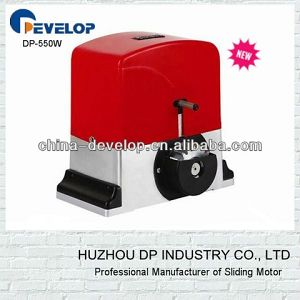
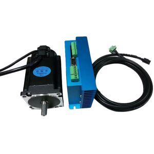
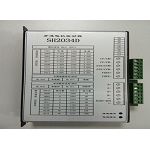
Instruction manual of 2 phase combined stepper motor drive
DCH-20403M series
Controlled by constant current with stable running and reliable performance
Technology Feature
10V~40V DC power supply, H bridge, double pole, constant phase current drive
8 output current with the max is 3A for selection, 7 sifting models for selection with the max sifting is 64. Input signal is optical separation, 20403M standard common cathode single impulse connection port, 20403M standard common anode single impulse connection port
Reserve performance when power off: the semi-closed frame can be used under environment with strict requirement. It has automatic half-current lock performance, which can save energy.
Electrical Characteristics(TI=25?)
Power supply voltage | 10V~40V DC, capacity 0.03KVA |
Output current | Max, 3A/phase, current can be set by the switch |
Drive way | Constant current controlled by PWM |
Magnetization | Whole, half, 4 sift, 8 sift, 16 sift and 64 sift |
Insulated resistance | >100MO under normal temperature and pressure |
Insulated strength | 0.5KW, 1 minute under normal temperature and pressure |
Use Environment and Parameter
Cooling ways | Nature cooling, it needs radiator if it is used under bad environment | |
Use environment | Site | Avoid dust, oil and corrosion air |
Temperature | 0?~+50? | |
Humidity | 80%RH, no froze dew and frost | |
Vibration | 5.9m/s3 Max | |
Save temperature | -20?~+65? | |
Outside dimension | 116×60×37mm | |
Weigh | About 0.21 Kg | |
Power Supply Voltage
The design of inside switching power supply can provide a wide voltage range, which can adjust between 10V and 40V (DC) as the customer required. Usually, the high rated voltage can improve the high speed torque of the motor but the consumption is also much highly and the temperature will increase highly.
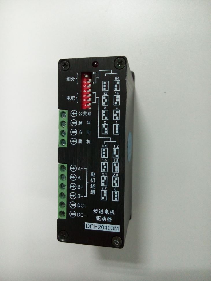
Output Current Selection
The max output current of the drive is 3A/phase, it has 8 selections by different choose with No.5, 6, 7 switch on the drive panel, and there will be 8 different currents accordingly from 0.9A to 3A, which can be used for different motors. Please refer to the current selection table.
Note: The actual switch position is opposite to the white square on the panel.

Sifting Selection
There are 7 different running models, whole, half, 4, 8, 16, 32 and 64 sifting, it can has been realized by the different selections with No. 1, 2 and 3 switches on the panel.
Note: The actual switch position is opposite to the white square on the panel.

Automatic Half-current
The drive will run with energy-saving condition (half current) if there is no impulse signal within half second, and the phase current of motor winding will reduce to the half of the setting value, which will reduce the consumption of motor and drive. But the output torque of the motor will reduce accordingly. The drive will go back to the rated value when the next impulse comes.
Incorrect Phase Protection
The customer is easy to wire incorrectly when connect the 2 phase motor to the drive, which will result in the drive is damaged. The drive is designed with incorrect phase protective circuit, so even the customers wire incorrectly, the drive will not be damaged but the motor can not run normally at that time. Usually, when it happens, it will have small force. In case of that, please check the wiring.
Radiation
Most breakdowns are caused by working under over high temperature, so the effective heating radiation can improve the reliability and service life. It is recommended to fix the drive toughly on metal case, then the bottom panel will help I to radiate. It can also add silicon grease as the conductive material on it if possible. Surely, the temperature will be better control if there is a radiating fan outside.
Input Signal
Public port: DCH-20403M drive adopts common cathode wiring way, the user connect the cathode of input signal to the terminal, and connect the input signal to the relative signal terminal. It will be effective when the power level is low the time when the inside optical couple is conductive, and the control signal input into the drive.
Impulse signal input: The impulse signal under common cathode will decrease and will be encoded as an effective impulse by the drive, and it will drive the motor to run. To make sure the reliable response of the impulse signal, the last time during lower power level impulse under common cathode should be more than 10µs. The response frequency of the drive is 70 KHz, the over high frequency will not be response.
Direction Signal Input: The low and high power level signal is to control the 2 rotate direction of the motor. It means high power level input when during the common cathode.
Make sure the direction signal is at least 10µs before the impulse signal when control the rotate direction of the motor, for it can avoid the response for the wrong impulse.
Power-of Signal Input:
It receives the high/low power level signal form the control case, the motor current will be shut off when the common cathode with high power level and the rotor will be locked.

Note: ?The wiring of the drive (DCH-20403MB) input signal is common cathode way. The low power level of the controller is connected to the public port of the drive, the impulse, direction and power-off signal of controller is still connected to impulse, direction and power-off signal of the drive. ?The customer should specify in advance if want to by the common anode drive, otherwise we will provide common cathode drive
Signal Requirement
The drive is controlled by single impulse (common cathode/anode). Impulse, direction and power-off signal is separated by the optical coupling. The current should be between 5mA~12mA to make sure the optical coupling well work. The current-limit resistance inside the optical coupling is 510O, +5V power level. It can add resistance to limit the current as you required when the input voltage is higher.
e.g. The input power level is +24V, it should connect in series with 2.4KO (0.25W) resistance in each signal.
If the input power level is +12V, t should connect in series with 1KO (0.25W) resistance in each signal.
Note: Current-limit resistance can not connect to the public port of the drive.
Typical Wiring Drawing

Note:
In order to use the drive properly, please separate the power wiring (motor phase wiring, power supply wiring) to the weak power wiring, which will avoid the signal being interrupted. If it can not wire separately or it can not identify whether there is strong interrupted substance (transformer, magnetic valve) or not, it had better to use H-cable to transfer the signal. The higher power level control signal is also interrupted resistance.
Outside Dimension

-
DC Side Motor 1 Pieces / (Min. Order)

-
DC Door Motor 1 Pieces / (Min. Order)
-
Door Motor 1 Pieces / (Min. Order)
-
Door Motor 1 Pieces / (Min. Order)
-
Door Motor 1 Pieces / (Min. Order)
-
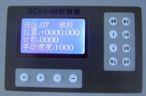
DCYJ-08 1 Pieces / (Min. Order)
-
DCYJ-208 1 Pieces / (Min. Order)
-
19-ZDC-07-HD1 1 Pieces / (Min. Order)

-
21-ZDC-07-HHT2 1 Pieces / (Min. Order)

-
64-ZDC-07-MEDG25 1 Pieces / (Min. Order)

-
66-ZDC-06-KS 1 Pieces / (Min. Order)

-
55-ZDC-03-NF 1 Pieces / (Min. Order)

-
DC Torque Motor 1 Pieces / (Min. Order)
-
Z4 DC Motors 1 Pieces / (Min. Order)
-
Dc Motor-16HY 1 Pieces / (Min. Order)
-
Dc Motor-14HY 1 Pieces / (Min. Order)
-
Dc Motor-17HD 1 Pieces / (Min. Order)
-
Dc Motor-23HD 1 Pieces / (Min. Order)
-
Dc Motor-17HY 1 Pieces / (Min. Order)
 Favorites
-
 Stepper Motor With Encoder Feedback
1 Pieces / (Min. Order)
Stepper Motor With Encoder Feedback
1 Pieces / (Min. Order)
-
DCYJ-208
1 Pieces / (Min. Order)
-
 CF2034D
1 Pieces / (Min. Order)
CF2034D
1 Pieces / (Min. Order)
-
 130ST-M15025
1 Pieces / (Min. Order)
130ST-M15025
1 Pieces / (Min. Order)
-
 130ST-M15015
1 Pieces / (Min. Order)
130ST-M15015
1 Pieces / (Min. Order)
-
 80ST-M03230
1 Pieces / (Min. Order)
80ST-M03230
1 Pieces / (Min. Order)
-
 80ST-M02430
1 Pieces / (Min. Order)
80ST-M02430
1 Pieces / (Min. Order)
-
 80ST-M01630
1 Pieces / (Min. Order)
80ST-M01630
1 Pieces / (Min. Order)
-
 60ST-M01930
1 Pieces / (Min. Order)
60ST-M01930
1 Pieces / (Min. Order)
-
 110S5P261-3010A
1 Pieces / (Min. Order)
110S5P261-3010A
1 Pieces / (Min. Order)
-
 110SH3P243-5203A
1 Pieces / (Min. Order)
110SH3P243-5203A
1 Pieces / (Min. Order)
-
 110SH3P202-4803A
1 Pieces / (Min. Order)
110SH3P202-4803A
1 Pieces / (Min. Order)
-
 110SH3P161-4203A
1 Pieces / (Min. Order)
110SH3P161-4203A
1 Pieces / (Min. Order)
-
 110SH3P128-4203A
1 Pieces / (Min. Order)
110SH3P128-4203A
1 Pieces / (Min. Order)
-
 86SH3P130-5803A
1 Pieces / (Min. Order)
86SH3P130-5803A
1 Pieces / (Min. Order)
-
 86SH3P130-22503A
1 Pieces / (Min. Order)
86SH3P130-22503A
1 Pieces / (Min. Order)
-
 86SH3P101-5803A
1 Pieces / (Min. Order)
86SH3P101-5803A
1 Pieces / (Min. Order)
-
 86SH3P101-2003A
1 Pieces / (Min. Order)
86SH3P101-2003A
1 Pieces / (Min. Order)
-
 130S281-6004A
1 Pieces / (Min. Order)
130S281-6004A
1 Pieces / (Min. Order)
 Frequent updates ensuring high quality data
 Over 5000 customers trust us to help grow their business!


 Menu
Menu