 Menu
Menu


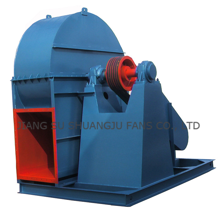
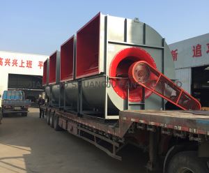
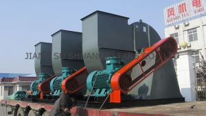
Low and Medium | Middle Pressure High Flow FD Centrifugal Fan | Blower Design 4-72 Series
-
Min Order
1
-
Product Unit
Pieces
-
Origin
China Mainland
-
Payment


- Contact Now Start Order
- Favorites Share
- Description
Product Detail
PURPOSE
Type 4-72 centrifugal fan can be used as ventilation and air exchange in the rooms of general plants and large buildings or transferring air and other gases which are non-natural, non-explosive, non-volatile, non-harmful for human body and non-corrosion for steels. Type B4-72 centrifugal fan can handle combustible and volatile gases, Type F4-72 centrifugal fan is mainly used to handle the corrosive gas. Adhesive matter is not permitted in the gas which handled by Type 4-72, B4-72 and F4-72 centrifugal fan, dust and hard particle content in the gas is not greater than 150mg/m3. The gas temperature shall not exceed 80?.
The performance, optional part table and foundation dimension of Type B4-72 are the same as Type 4-72, it can be selected according to the sample. The structure of the fan is the same basic as Type 4-72, Type B35 motor with flanges and feet is used for ?2.8A~6A, series YB in the table is selected for ?6~12C,D motor, the mounting mode is B.
Type F4-72 centrifugal fan are made of stainless steel, glass fiber reinforced plastics or other corrosion resisting materials, its performance and foundation dimension are the same as Type 4-72 centrifugal fan.
Type 4-72 centrifugal fan is the fan which used in our country in the early stage, however, it is the popular fan for use, from the high building to subway, from the boiler blasting to workshop ventilation, from the Northern Frontier to the South China Sea Shore, from the Western Plateau to the Eastern Border Area, Type 4-72 centrifugal fan can be seen everywhere.
TYPE
Viewing from the motor end, if the impeller rotates in clockwise, it is called a right rotating fan and symbolized with “right”, on the contrary, if the impeller rotates in counter clockwise, it is called a counter clockwise fan and symbolized with “left”. The outlet position of the fan can be expressed from the outlet angle of the casing, ?2.8~6 is made of one angle 0°, user can change the angle according to the requirement, without note when ordering. Among them, adjustment of angles for ?2.8~6 outlet angle is 0°~225°, the interval is 45°; ?3.2~6 outlets is 0°~225°, the interval is 22.5°adjustment of angles for ?8~12 outlets is 0°~225°, the interval is 45°; adjustment of angles for ?16?20 can be made three kinds of angles which are 0°?90°?180°and can not be adjusted, note when ordering.There are 4 driving modes: A,B, C, D: In Type 4-72 fan, ?2.8~5 take mode A, ?6 takes modes A and C, ?8~12 take modes C and D, ?16~20 take mode B.
If the above machine ??driving mode and outlet angle can’t meet your requirement, our factory has ability to transform and design the fan for you until you are satisfied with it.
STRUCTURE
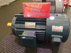
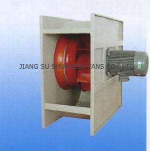
?2.8A~6A of Type 4-72 centrifugal fan mainly consist of impeller, casing, air intake and motor etc. ?6C and ?8~20 with driving unit except the above structure.
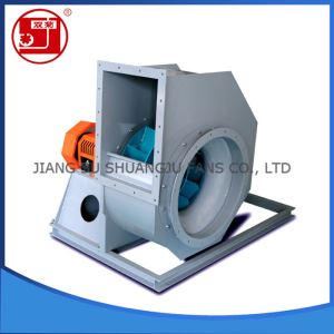
Impeller — The impeller consists of 10 backward wing blades, a curved front disc and flat rear disc, they are made up of steel plate, (B4-72 impeller is made up of cast aluminum alloy), the impeller shall be balanced statically and dynamically, over speed running test is carried out, and thus it has smooth running and the aerodynamic performance is good.
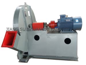
Casing — it shall be made two kinds of different types, among them: ?2.8~12 casing is made in integral type, it can not be disintegrated. ?16~20 casing is made in three-open type, besides the casing is divided into two parts along the split horizontal level, the upper casing is vertically divided into two parts again along the center-line, and they are fixed by bolts, and thus facilitate to put into or take out the impeller.
Inlet — the inlet is manufactured as an integral type, the inlet is generally fixed on the side of the fan, the section which is parallel to the shaft is curved forms and gas is allowed into the impeller smoothly with a little loss.
Driving unit — it consists of shaft, bearing box, rolling bearing, belt pulley or coupling.
PERFORMANCE AND SELECTION
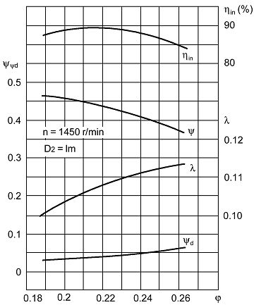
The sample only gives the non-dimensional performance table and characteristic curve for ?10 sample fan, the dimensional performance parameter for other machine number can be calculated.
Table 1 Non-dimensional Performance of Type 4-72 ? 10 Sample Fan
1 | 2 | 3 | 4 | 5 | 6 | |
f | 0.1884 | 0.2051 | 0.2218 | 0.2361 | 0.25 | 0.2637 |
Fig.1 Non-dimensional Performance Curve of Type 4-72 ? 10 Sample Fan | The calculation formula calculating Dimensional parameter from non-dimensional parameters as follow:
|
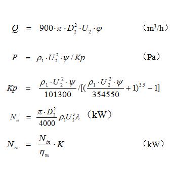
Where:
Q — Flow rate (m3/h) Nin — Inner power (kW)
P — Total pressure(pa) P1 — Suction density (kg/m3)
Nre — Required power(kW) K — Motor conservative factor
?m — Mechanical efficiency
kp — Total pressure compressibility factor
D2 — Outer edge diameter of impeller blade (m)
U2 — Outer edge linear speed of impeller blade (m/s)
The performance of the fan normally indicates the performance of transferring air under the standard state. The so-called standard state indicates atmospheric pressure Pa=101325 Pa, atmospheric temperature t=20?, relative humidity x=50%. air density ?=1.2kg/m3, when the operating condition is non standard, the performance of non-standard condition must be converted into a standard condition performance, then select a fan according to the table,the conversion formula are as follows:
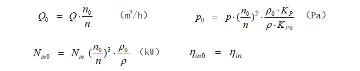
Where:
With footnote 0 symbolizes the standard state,without footnote 0 symbolizes the service state.
Table 2 mechanical efficiency
Driving mode | Motor directly connecting | coupling | V—belt |
?m | 1 | 0.98 | 0.95 |
Table 3 Motor conservative factor
Shaft power kW | < 0.5 | > 0.5~1 | >1~2 | > 2~5 | > 5 |
K | 1.5 | 1.4 | 1.3 | 1.2 | 1.15 |
During operation, excessive or lack flow rate is often existed. The reasons are many ones. If this phenomenon occurs during the operation, the reason may be that the drag in the pipeline is great sometime or small sometime. If the drag is successively reduced for a long time during operating or the drag is suddenly reduced in a short time, it may mainly be the pipeline to be plugged. When a fan is installed and excessive or lack flow rate is occurred during normal running,the reasons have mainly two aspects:
1. The actual and theoretic values k of resistance in pipe net is widely different. It was known normal pipe net characteristic equation: P=KQ2, if the actual value k is less than the theoretic value k, the flow rate increases; vice versa, flow rate decreases, see Fig.2.
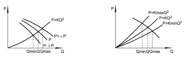
Fig 2 The relationship between pipe net characteristic and total Pressure deviation or flow rate
2. The effect of fan total pressure deviation ?p have not been considered during selecting. when the actual total pressure of fan is a positive deviation, the flow rate increases, and when it is a negative deviation, the flow rate decreases.
The flow rate excess or in sufficient occurred after fan newly installing and when putting into operation, one of the following methods can be used to eliminate:
a. Flow rate can be adjusted by damper opening and closing.
b. Flow rate can be adjusted by changing the speed of the fan.
c. Flow rate can be adjusted by changing a higher or lower pressure fan.
d. Flow rate can be adjusted by changing pipe net resistance, and using the resistance coefficient of pipe net.
It must be pointed out: flow rate is normally adjusted by damper, but when the actual flow rate is much greater than the required, it wastes power, if the condition permits reducing fan speed or change-over a lower pressure fan.
When the damper is full open, the flow rate is still insufficient, at this moment, the damper has lost its function, so try to reduce the resistance coefficient of pipe net, or increase the speed of the fan, or change-over a higher pressure fan, but the fan driven by motor and coupling can not be normally changed the speed, only the fan driven by belt, the speed can be increased and decreased by the means of changing the size of belt pulley diameter, the max. speed must be lower than that listed in the performance table, and the motor power shall be calculated.
PURCHASE INFORMATION
When purchasing, indicate the fan size, flow rate, pressure ,discharge angle, rotation direction and the motor model, power and speed etc.
-
One-side Welding (parallel Welding), Intermediate Frequency Inversion Welding Machine 1 Pieces / (Min. Order)
-
desktop table design fiber laser marking machine used as metal marking and plastics marking, with advanced design and technology 1 Pieces / (Min. Order)
-
MU006 Stainless Steel Barware Cocktail & Bar & Ice & Drink & Juice Muddler Mixing Spoon Crusher Pestle Stirrer with Round Base 1 Pieces / (Min. Order)
-
MU005 Stainless Steel Barware Cocktail & Bar & Ice & Drink & Juice Muddler Mixing Spoon Crusher Pestle Stirrer Eco-Friendly 1 Pieces / (Min. Order)
-
MU004 Stainless Steel Barware Cocktail & Bar & Ice & Drink & Juice Muddler Mixing Spoon Crusher Pestle Stirrer with ABS Base 1 Pieces / (Min. Order)
-
MU002 Stainless Steel Barware Cocktail & Bar & Ice & Drink & Juice Muddler Mixing Spoon Crusher Pestle Stirrer with ABS Base 1 Pieces / (Min. Order)
-
Gas Analysis System For Cement Kiln Process 1 Pieces / (Min. Order)
-
Gas Analysis Of Cement Kiln Process 1 Pieces / (Min. Order)
-
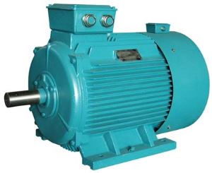
YVFF-H Series Frequency Conversion Three-phase Adjustment Speed Asynchronous Marine Motor 1 Pieces / (Min. Order)
-
OD32mm 2 pin,3 pin,4 pin high current compact design connector 1 Pieces / (Min. Order)
-
New Design Car Alloy Wheels 17 Inch 5x114.3 Deep Dish Rims For Sale White Car Wheel Rims Universal 1 Pieces / (Min. Order)
-
Double-sided PET Adhesive Tape with Different Adhesive in Both Sides 1 Pieces / (Min. Order)
-
Used For Roadway Breaking Old Road Surface Finishing Industrial And Mining Enterprises Destroy Concrete Foundation Pneumatic Hammer 1 Pieces / (Min. Order)

-
Oil Chemical Aluminum Alloy Housing High Pressure Mercury Explosion Proof Light 1 Pieces / (Min. Order)
-
ATEX High Lumen Output T5 Tube Explosion Proof Fluorescent Extension Light Fixtures 1 Pieces / (Min. Order)
-
Best selling high quality and low price of double screw cone mixer 1 Pieces / (Min. Order)
-
Safest Glass Baby Feeding Bottles 180ml with Soft Nipple | the Best Baby Milk Feeding Bottle 1 Pieces / (Min. Order)

-
Instead Traodational Lead Anode ,Newly Titanium based Lead Dioxide Anode for Electrowinning Industry 1 Pieces / (Min. Order)
-
Headphone Case, Protective Hard Carry Case For Traveling. Universal Headset Case , Water Resistant And Suitable For Most Headphones And Headsets 1 Pieces / (Min. Order)
-
Low Building Clearance Explosion-proof Bridge Crane Design with Cap, 32T 1 Pieces / (Min. Order)
 Favorites
-
 Advantages of Three Phase Induction Asynchronous Motors YVF2 Series Types, Uses and Voltage
1 Pieces / (Min. Order)
Advantages of Three Phase Induction Asynchronous Motors YVF2 Series Types, Uses and Voltage
1 Pieces / (Min. Order)
-
 High Pressure Commercial Extractor Centrifugal Fans | Air Blower 9-19 9-26 Series
1 Pieces / (Min. Order)
High Pressure Commercial Extractor Centrifugal Fans | Air Blower 9-19 9-26 Series
1 Pieces / (Min. Order)
-
 Low and High Static Pressure High Volume Low Flow Low Noise Centrifugal Fan THF Series
1 Pieces / (Min. Order)
Low and High Static Pressure High Volume Low Flow Low Noise Centrifugal Fan THF Series
1 Pieces / (Min. Order)
-
 Single Inlet Low Pressure High Volume Inline Duct Centrifugal Exhaust Fans with Ceiling Vent | Roof Ventilation DDF Series Shop
1 Pieces / (Min. Order)
Single Inlet Low Pressure High Volume Inline Duct Centrifugal Exhaust Fans with Ceiling Vent | Roof Ventilation DDF Series Shop
1 Pieces / (Min. Order)
-
 Low, Medium and High Static Pressure Low Cfm Industrial Exhaust Centrifugal Fans 4-79 4-2X79 Series
1 Pieces / (Min. Order)
Low, Medium and High Static Pressure Low Cfm Industrial Exhaust Centrifugal Fans 4-79 4-2X79 Series
1 Pieces / (Min. Order)
-
 Explosion Proof Exhaust Centrifugal Industrial Extractor Exhaust Fans | Induced Draft Blower B4-68 Series
1 Pieces / (Min. Order)
Explosion Proof Exhaust Centrifugal Industrial Extractor Exhaust Fans | Induced Draft Blower B4-68 Series
1 Pieces / (Min. Order)
 Frequent updates ensuring high quality data
 Over 5000 customers trust us to help grow their business!


 Menu
Menu