 Menu
Menu


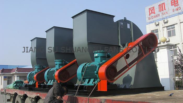
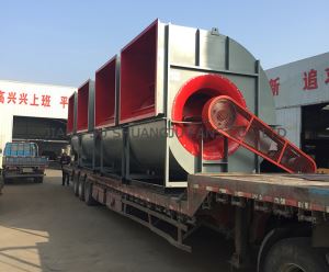
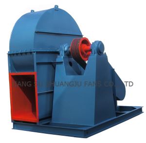
Explosion Proof Exhaust Centrifugal Industrial Extractor Exhaust Fans | Induced Draft Blower B4-68 Series
-
Min Order
1
-
Product Unit
Pieces
-
Origin
China Mainland
-
Payment


- Contact Now Start Order
- Favorites Share
- Description
Product Detail
PURPOSE
Type 4-68 centrifugal fan can be used as ventilation and air exchange in the rooms of general plants and large buildings or transferring air and other gases which are non-natural, non-explosive, non-volatile, non-harmful for human body and non-corrosion for steels. Type 4-68 centrifugal fan, dust and hard particle content in the gas is not greater than 150mg/m3. The gas temperature shall not exceed 80?.
TYPE
The fan is made as a single suction. There are 12 types of fan numbers which are 2.8, 3.15, 3.55, 4, 4.5, 5, 6.3, 8, 10, 12.5, 16 and 20.
The fan can be made of 2 types of rotation i.e, right and left. Viewing from one end of the motor, it is called as clock-wise fan if the impeller rotates clock-wise, symbolized with “right”, On the contrary, it is called as counter-clock-wise fan if the impeller rotates counter-clockwise, symbolized with “left”.
The outlet position of the fan can be expressed from the outlet angle of the casing. It can be made 6 kinds of angles which are 0°, 45°,90°, 135°,180°,225°,from both “Right” and “left”.
The fan driving mode is three kinds of mode A (?4~6.3), mode D and mode C (?7.1~16).
There are 4 driving modes: A,B,C,D: ?2.8~5 take mode A, ?6.3~12.5 takes modes C and D, ?16,20 take mode B.
STRUCTURE
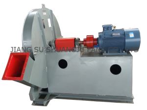
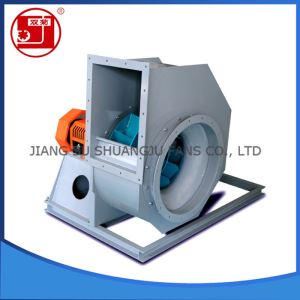
?2.8A~5A of Type 4-68 centrifugal fan mainly consist of impeller, casing, air intake and motor etc. ?6.3~20 with driving unit except the above structure.
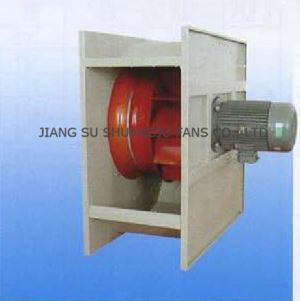
Impeller — It consists of 12 backward curved blades welded between curved front disc and flat rear disc. It is made of steel plate, and it shall be balanced statically and dynamically, thus it guarantees a smooth operation.
Casing — To be welded into a volute with normal steel plate.it shall be made two kinds of different types, among them: ?2.8~5 casing is made in integral type, it can not be disintegrated. ?16~20 casing is made in three-open type, besides the casing is divided into two parts along the split horizontal level, the upper casing is vertically divided into two parts again along the centerline, and they are fixed by bolts, and thus facilitate to put into or take out the impeller.
Inlet — To be integrated into a convergent streamlined structure and bolted on the suction side of the casing.
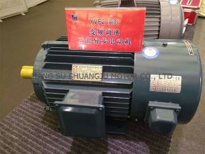
Driving unit — It consists of shaft, bearing box, rolling bearing, belt pulley or coupling. The main shaft is made of super steel. The integral bearing box is used for 4 types of ?6.3~12.5 which installed with thermometer and oil level indicator. Two side by side pedestals are used for the two type fans of ?16B and 20B. Thermometer is installed on pedestal and it lubricated by bearing grease.
PERFORMANCE AND SELECTION
The fan performance is converted with non-dimensional performance curve (Fig.1)and non-dimensional performance of operation condition point(table.1):
The dimensional parameter formula is calculated with non-dimensional parameter.
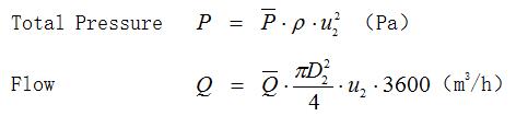
Where:
D2 — Outer edge diameter of impeller blade (m)
u2 — Outer edge linear speed of impeller blade (m/s)
? — Suction density (kg/m3)
1. The designer and user shall select fan type and motor from performance table according to the required flow rate and total pressure.
2. The performance of each speed in performance table is that the performance within of maximum efficiency of 90% can be divided into seven performance points according to the flow rate, the performance table can be as a standard when purchasing, order.
3. The performance of qualified product of fan ex-works is that the value of total pressure under the given flow rate shall not exceed ±5%.
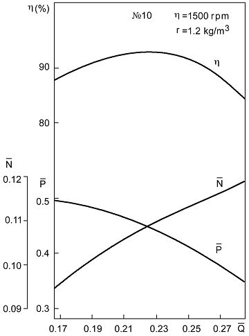 | Fig.1 Non-dimensional Performance Curve of Type 4-68 ? 10 Sample Fan |
Table 1 non-dimensional performance table of type 4-68 centrifugal fan.
Code | Operation condition point | ||||||
1 | 2 | 3 | 4 | 5 | 6 | 7 | |
| 0.165 | 0.185 | 0.205 | 0.225 | 0.245 | 0.265 | 0.285 |
| 0.498 | 0.487 | 0.472 | 0.450 | 0.422 | 0.388 | 0.350 |
? | 0.876 | 0.903 | 0.922 | 0.930 | 0.920 | 0.885 | 0.847 |
N | 0.094 | 0.100 | 0.104 | 0.109 | 0.112 | 0.116 | 0.118 |


The above figure and table are only used when Re =5×10⁶. The relative correction is carried out according to the test result when Re =5×10⁶.
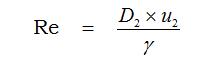
Where:
Re — Reynolds number
D2 — diameter of outside end of impeller blade(m)
u2 — line speed of outside end of impeller blade(m/s)
? — coefficient of kinematic viscosity(0.15×10⁻⁴m2/s)
4. The parameter given in the performance table is calculated with air medium: gas temperature t=20?, atmosphere P=101325Pa, gas density ?=1.2kg/m3.
5. When the operation condition is non-standard, the performance is calculated with following formula:
? Conversion formula for changing density ?, speed n:

? conversion formula for changing speed n, atmosphere Pa, and gas temperatu
-re t:
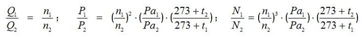
Where:
With footnote 2 symbolizes the standard state, footnote 1 symbolizes the service state.
6. In performance table:
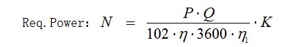
Where:
Q — flow (m3/h)
? — total pressure efficiency
P — total pressure(Pa)
?1 — mechanical efficiency, select according to table 2
Table 2
Driving mode | Mechanical efficiency |
Motor directly drive | 1.00 |
Coupling directly drive | 0.98 |
V belt driving | 0.95 |
Table 3
Shaft power | Motor conservative factor |
< 0.5 | 1.5 |
>0.5~1 | 1.4 |
>1~2 | 1.3 |
>2~5 | 1.2 |
>5 | 1.15 |
The selected motor power should not be less than the required power.
7. Treatment for excessive or insufficient flow rate:
The phenomenon of flow excess or insufficient often occurs when use,there are many reasons of occurring such phenomenon.If the phenomenon of flow some times large and sometimes small occurs during,the main reason is due to resistance in pipe net sometimes great and or sometimes small.If it is gradually reduced through longer time or suddenly reduced within short time,the main reason is that the fan passage or pipe net is plugged.
The phenomenon of flow excess or insufficient will occur during normal running after newly installing, the main reasons are as follows:
(1)The actual and calculated values of pipe net resistance is widely different. It was known normal pipe net characteristic equation p=µ Q2 (µis the coefficient of resistance),if the actual value µ is less than the calculated value µ,the flow rate increases; vice versa, flow rate decreases.
(2)The effect of fan total pressure deviation ?p have not been considered during selecting,when the actual total pressure of fan is positive deviation,the flow rate increases,and when it is negative deviation,the flow rate decreases.
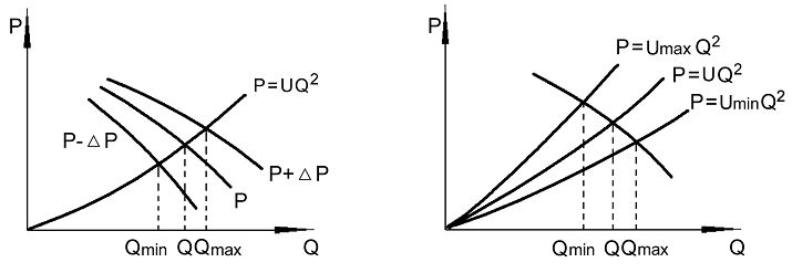
Fig 2 The relationship between pipe net characteristic and total Pressure deviation or flow rate
The flow rate excess or in sufficient occurred after fan newly installing and when putting into operation, one of the following methods can be used to eliminate:
a. Flow rate can be adjusted by damper opening and closing.
b. Flow rate can be adjusted by changing the speed of the fan.
c. Flow rate can be adjusted by changing a higher or lower pressure fan.
d. Flow rate can be adjusted by changing pipe net resistance, and using the resistance coefficient of pipe net.
It must be pointed out: flow rate is normally adjusted by damper, but when the actual flow rate is much greater than the required, it wastes power, if the condition permits reducing fan speed or change-over a lower pressure fan.
When the damper is full open, the flow rate is still insufficient, at this moment, the damper has lost its function, so try to reduce the resistance coefficient of pipe net, or increase the speed of the fan, or change-over a higher pressure fan, but the fan driven by motor and coupling can not be normally changed the speed, only the fan driven by belt, the speed can be increased and decreased by the means of changing the size of belt pulley diameter, the max. speed must be lower than that listed in the performance table, and the motor power shall be calculated.
PURCHASE INFORMATION
When purchasing,,indicate the fan size, flow rate, pressure, discharge angle, rotation direction and the motor model, power and speed etc.
-
GFG Series Efficient Boiling Dryer 1 Pieces / (Min. Order)
-
QG Series Of Internal And External Wall Of Steel Pipe Special Shotblast Cleaning Machine 1 Pieces / (Min. Order)
-
GFG Series High Efficient Fluidizing Drier 1 Pieces / (Min. Order)
-
YZH79 Series High Efficient Powder Automatic Forming Hydraulic Press 1 Pieces / (Min. Order)
-
GFG Series High Efficient Fluidizing Drier 1 Pieces / (Min. Order)
-
German Imports Inkjet Printer / German KBA / White Ink Inkjet Printer 1 Pieces / (Min. Order)

-
GFG Series Efficient Boiling Dryer 1 Pieces / (Min. Order)
-
GFG Series Efficient Boiling Dryer 1 Pieces / (Min. Order)
-
DX - W Series Industrial Chiller Parameter Table (-20) 1 Pieces / (Min. Order)
-
GFG Series Efficient Boiling Dryer 1 Pieces / (Min. Order)
-
GFG Series Efficient Boiling Dryer 1 Pieces / (Min. Order)
-
SZL Double Drums Horizontal Chain Grate Biomass-fired Hot Water Boiler 1 Pieces / (Min. Order)
-
Non-standard Chain Plate Line Series 1 Pieces / (Min. Order)
-
CJW-2000 Integrated Mechanical And Electrical And Magnetic Particle Testing Machine 1 Pieces / (Min. Order)
-
Nylon Multi-monofilament Fishing Net 1 Pieces / (Min. Order)

-
GFG Series Efficient Boiling Dryer 1 Pieces / (Min. Order)
-
Model GC-1/22.5 Natural Gas Cylinder Pressure Testing Device 1 Pieces / (Min. Order)
-
Wholesale 8oz plastic single wall tumbler color customized tableware/drinkware cup 1 Pieces / (Min. Order)

-
APL American President Lines Limited Internation shipping service 1 Pieces / (Min. Order)

-
High Efficiency super quality warehouse industrial 240W LED High Bay Light with 5 years warranty Meanwell driver 1 Pieces / (Min. Order)
 Favorites
-
 Advantages of Three Phase Induction Asynchronous Motors YVF2 Series Types, Uses and Voltage
1 Pieces / (Min. Order)
Advantages of Three Phase Induction Asynchronous Motors YVF2 Series Types, Uses and Voltage
1 Pieces / (Min. Order)
-
 High Pressure Commercial Extractor Centrifugal Fans | Air Blower 9-19 9-26 Series
1 Pieces / (Min. Order)
High Pressure Commercial Extractor Centrifugal Fans | Air Blower 9-19 9-26 Series
1 Pieces / (Min. Order)
-
 Low and High Static Pressure High Volume Low Flow Low Noise Centrifugal Fan THF Series
1 Pieces / (Min. Order)
Low and High Static Pressure High Volume Low Flow Low Noise Centrifugal Fan THF Series
1 Pieces / (Min. Order)
-
 Single Inlet Low Pressure High Volume Inline Duct Centrifugal Exhaust Fans with Ceiling Vent | Roof Ventilation DDF Series Shop
1 Pieces / (Min. Order)
Single Inlet Low Pressure High Volume Inline Duct Centrifugal Exhaust Fans with Ceiling Vent | Roof Ventilation DDF Series Shop
1 Pieces / (Min. Order)
-
 Low, Medium and High Static Pressure Low Cfm Industrial Exhaust Centrifugal Fans 4-79 4-2X79 Series
1 Pieces / (Min. Order)
Low, Medium and High Static Pressure Low Cfm Industrial Exhaust Centrifugal Fans 4-79 4-2X79 Series
1 Pieces / (Min. Order)
-
 Low and Medium | Middle Pressure High Flow FD Centrifugal Fan | Blower Design 4-72 Series
1 Pieces / (Min. Order)
Low and Medium | Middle Pressure High Flow FD Centrifugal Fan | Blower Design 4-72 Series
1 Pieces / (Min. Order)
 Frequent updates ensuring high quality data
 Over 5000 customers trust us to help grow their business!


 Menu
Menu