 Menu
Menu


Graphic LCD Smart Display
-
Min Order
1
-
Product Unit
Pieces
-
Origin
China Mainland
-
Payment


- Contact Now Start Order
- Favorites Share
- Description
Product Detail
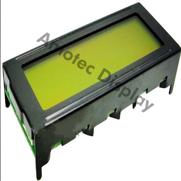
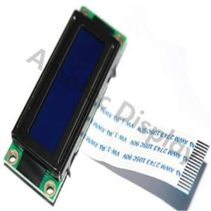
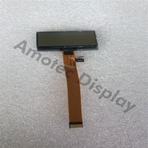
Graphic LCD Smart Display
Graphic LCD Smart Display ADM12232D
Model No. ADM12232D
?Graphic LCD Smart Display122x32, Display LCD 122x32
?Monochrome Graphic LCD
?Built-in controller (S1D15200 DOA or equivalent)
?+5V power supply
?1/32 duty cycle
?8 bits parallel data
Description of Graphic LCD Smart Display ADM12232D
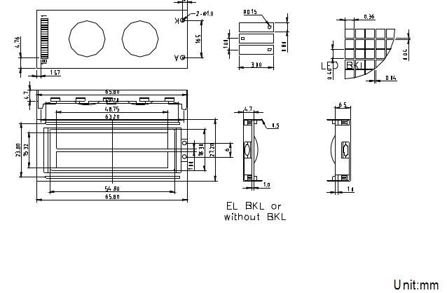
Graphic LCD Smart Display ADM12232D is a 122x32 graphic LCD module which is having the outline size 65.8 x 27.2 mm and AA size of 48.75 x 15.32 mm. This 122x32 Graphic LCD Smart Display is built in with S1D15200 DOAcontroller IC or equivalent IC.It supports 8-bit parallel interface and 5V power supply.
Features
1. 122dots x 32 dots
2. Built-in controller (S1D15200DOA or Equvalent)
3. 1/32 duty cycle
4. +5V power supply
5. LED side light
6. 8 bits parallel data
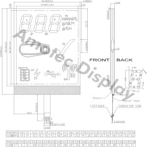
Mechanical diagram
Absolute Maximum Ratings
Item | Symbol | Min | Max | Unit |
Power Voltage | VDD -VSS | 0 | 7.0 |
V |
Input Voltage | VO | VSS | VDD | |
Operating Temperature Range | TOP | 0 | +50 | ? |
Storage Temperature Range | TST | -10 | +60 |
*Wide temperature range is available
(operating/storage temperature as –20~+70/-30~+80?)
Description Of Terminals
Pin | Pin Name | Input/ Output | External | Function |
1 | VSS | — | Power Supply | Signal ground for LCM |
2 | VDD | — | VDD: +5V | |
3 | VO | — | VLCD adjustment | |
4 | RST | Output | MPU | Signal ground |
5 | E1 | Input | MPU | Chip enable active “L”, SEG(1~61) |
6 | E2 | Input | MPU | Chip enable active “L”, SEG(62~122) |
7 | R/W | Input | MPU | Read/Write select signal |
8 | A0 | Input | MPU | Register select input |
9-12 | DB0-DB3 | Input/output | MPU | Low-order lines of data bus with 3-state, Bi-directinal function foe use in data |
13-16 | DB4-DB7 | Input/output | MPU | High-order lines of data bus with 3-state, Bi-directional function for use in data |
17 | NC | |||
18 |
Contrast adjust
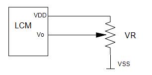
VDD-Vo:LCD DRIVING VOLTAGE
VR:10K~20K
DC Electrical Characteristics
Parameter | Symbol | Conditions | Min. | Type | Max. | Unit |
Supply voltage for LCD | VDD-VO | TA=25? | — | 4.6 | — | V |
Input voltage | VDD |
| 3.0 | — | 5.5 | V |
Supply current | IDD | VDD=5.0V;TA=25? | — | — | 1.5 | mA |
Input leakage current | ILKG |
| — | — | 1.0 | µA |
“H” level input voltage | VIH |
| 2.2 | — | VDD | V |
“L” level input voltage |
VIL | Twice initial value or less |
0 | — |
0.6 |
V |
“H” level output voltage | VOH | LOH=0.25mA | 2.4 | — | — | V |
“L” level output voltage | VOL | LOL=1.6mA | — | — | 0.4 | V |
Optical Characteristics
For STN Type Display Module (Ta=25?, VDD=5.0V±0.25V)
Item | Symbol | Condition | Min. | Typ. | Max. | Unit |
Viewing angle | ? | Cr=2 | -60 | - | 35 | deg |
F | -40 | - | 40 | |||
Contrast ratio | Cr |
| - | 6 | - | - |
Response time(rise) | Tr | - | - | 150 | 250 | ms |
Response time(fall) | Tr | - | - | 150 | 250 | ms |
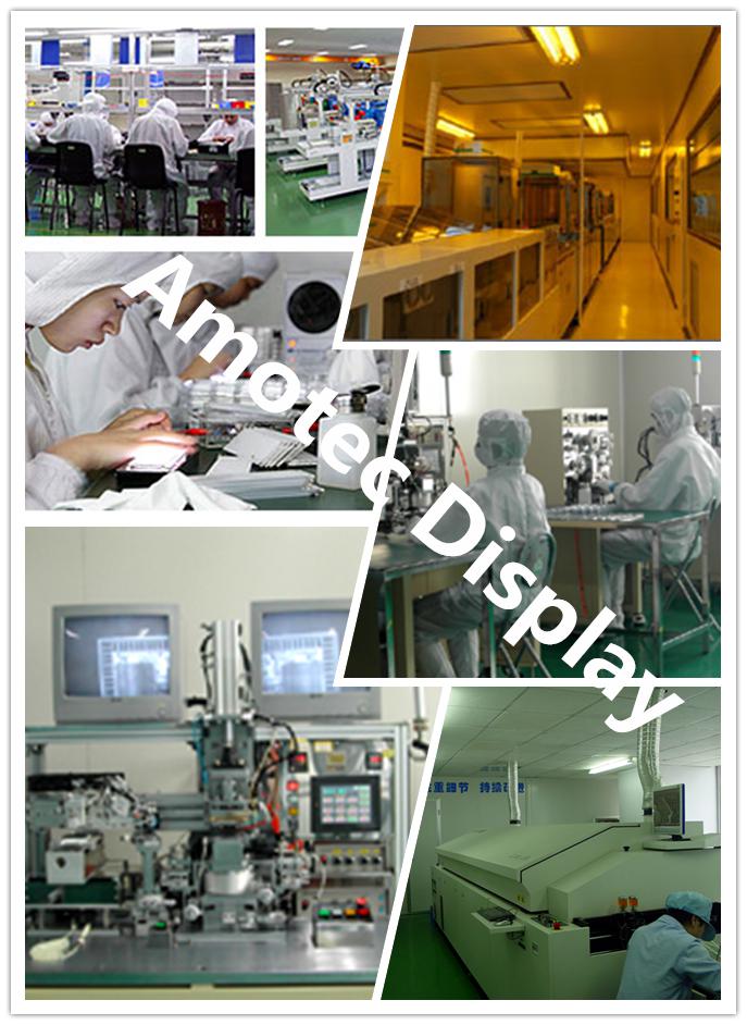
Amotec Display designs and manufactures standard and custom LCD display solutions. No matter you are creating a new product, replacing an obsolete part, or are looking for a more integrated partner, Amotec Display has the capabilities to take your production to the higher level.
FAQ
1. How to RESET (E2H)?
A0 | E (RD) | R/W (/WR) | D7 | D6 | D5 | D4 | D3 | D2 | D1 | D0 |
0 | 1 | 0 | 1 | 1 | 1 | 0 | 1 | 1 | 1 | 0 |
This command clears
The display start line register.
And set page address register to 3 page.
It does not affect the contents of the display data RAM.
When the power supply is turned on, a Reset signal is entered in the RES pin. The Reset command cannot be used instead of this Reset signal.
2.What is 8 bits parallel interface ?
In data transmission, parallel communication is a method of conveying multiple binary digits (bits) simultaneously. It contrasts with serial communication, which conveys only a single bit at a time; this distinction is one way of characterizing a communications link.
3.What is the difference between a parallel and a serial communication channel ?
The basic difference between a parallel and a serial communication channel is the number of electrical conductors used at the physical layer to convey bits. Parallel communication implies more than one such conductor. For example, an 8-bit parallel channel will convey eight bits (or a byte) simultaneously, whereas a serial channel would convey those same bits sequentially, one at a time. If both channels operated at the same clock speed, the parallel channel would be eight times faster. A parallel channel may have additional conductors for other signals, such as a clock signal to pace the flow of data, a signal to control the direction of data flow, and handshaking signals.
4.What is the application of parallel communication ?
Parallel communication is and always has been widely used within integrated circuits, in peripheral buses, and in memory devices such as RAM. Computer system buses, on the other hand, have evolved over time: parallel communication was commonly used in earlier system buses,
-
New Graphics Stand Up Paddle 1 Pieces / (Min. Order)
-
2G GSM Test Card 1 Pieces / (Min. Order)
-
Wcdma Nfc Test Card 1 Pieces / (Min. Order)
-
4G LTE Test Card 1 Pieces / (Min. Order)
-
Trophies And Awards 1 Pieces / (Min. Order)

-
Graphite Carbon 1 Pieces / (Min. Order)
-
Graphite Bars 1 Pieces / (Min. Order)
 Favorites
-
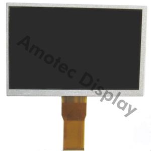 TFT LCD 7 Monitor
1 Pieces / (Min. Order)
TFT LCD 7 Monitor
1 Pieces / (Min. Order)
-
 Industrial LCD Panel
1 Pieces / (Min. Order)
Industrial LCD Panel
1 Pieces / (Min. Order)
-
 High Contrast LCD Display
1 Pieces / (Min. Order)
High Contrast LCD Display
1 Pieces / (Min. Order)
-
 LCD Graphic Display 128x64
1 Pieces / (Min. Order)
LCD Graphic Display 128x64
1 Pieces / (Min. Order)
-
 Low Power LCD Display
1 Pieces / (Min. Order)
Low Power LCD Display
1 Pieces / (Min. Order)
-
 Character LCD Display Panel
1 Pieces / (Min. Order)
Character LCD Display Panel
1 Pieces / (Min. Order)
-
 Digital LCD Display
1 Pieces / (Min. Order)
Digital LCD Display
1 Pieces / (Min. Order)
 Frequent updates ensuring high quality data
 Over 5000 customers trust us to help grow their business!


 Menu
Menu