 Menu
Menu


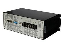
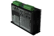
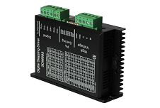
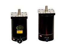
Brushless Motor Driver
-
Min Order
1
-
Product Unit
Pieces
-
Origin
China Mainland
-
Payment


- Contact Now Start Order
- Favorites Share
- Description
Product Detail
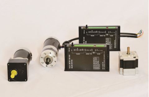
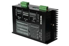
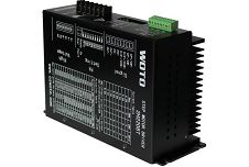
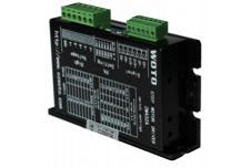
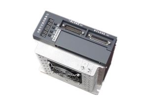
Brushless motor driver BLDC-5015A
Overview :
The brushless motor driver BLDC-5015 is suitable for three phase low voltage brushless DC motor which current is below 15A ,voltage is within 50V , applied widely in sewing machine . medical equipment .food machine .electric tools .garden machine etc .
Characteristic :
1.SPWM ,current .speed double closed loop , low speed high torque ,work stably .
2.High speed torque ,Max speed 98000rpm/min .
3.Max speed ratio is 1: 75 .
4.Flexible magnetic pole location setting ,60°/300°/120°/240°can be selected , suitable for different size motor .
5.Providing two way of speed adjustment .
6.Start and stop .quick brake ,photoelectric isolator
7.Output test speed ,alarm signal output
Parameter setting :
Output power supply | 24~50V DC power supply ,capacity :selected by power of motor |
Output current | Rated current 15A ,MAX instantaneous current is 45A |
Drive way | SPWM bipolar output drive |
Resistance | Under the condition of normal temperature and normal voltage >500MO? |
Insulation class | Under the condition of normal temperature and voltage 500V/minute |
Weight | About 300g |
Environment requirements :
Cooling way | Natural cooling |
Using environment | Avoid dust, oil mist and corrosive gases. |
Using temperature | 0ºC~+50ºC? |
Environmental humidity | <80%RH,No condensation, no frost |
Vibration | Couldn’t be over 5.7m/s2? |
Keeping | -20ºC~+125ºC,avoid dust |
Function and usage :
Power interface DC+ .DC :
DC 24 ~ 50V , linear power supply are always used for electric power supply ,ripple voltage shouldn’t be over 50VDC ,to avoid damaging the driver , the rated current of linear current shoule be over 60% of the output current of motor driver .when use power supply for electric ,it should mark thee rated output current .it is better to use the power supply that is suitable for the stepper motors.
Note : when connect wires , we should pay attention to the polar of the power supply , DC+ is cathode , DC- is anode , wrong connection will damage the driver .
Control signal definitive way :
1.Set by the potentiometer on the driver board , this way is suitable for fixed speed machine . When use the function , it need to adjust the the second of DIP into ON . User can be adjusted the stepper motor into needed speed according your requirements .
2.Set by interface of motor driver , this setting way is suitable for the machine with changed speed .when select the function , need to adjust the second DIP SW into OFF AVI accept the 0~5V simulation voltage instruction or PWM signal from supervisory controller .
SW2 | Source of instruction | Adjust way | Instruction Morphology | Current consume |
ON | Potentionmeter RV | CW need to increase speed ,CCW need to decrease the speed | - | - |
OFF | AVI interface | 0~5Vsimulation voltage:speed 60~rated speed | 0~5V simulation voltage | =5mA |
OFF | AVI interface | PWM signal | 1KHz duty ratio square wave | - |
Important note : the two control way , just can choose one .when the potentionmeter is not used , pls make the CCW into min value .
Motor start/stop signal (ENBL)
User can use the ENBL terminal to control the start or stop of the motor , this signal is photoelectric isolation. common anode is the inner 15V power supply of motor driver .The valid meaning of ENBL signal is inner photoelectric of driver which is turn on or turn off .when photoelectric turn on ,motor start work ; when photoelectric is off , motor stop work , the detailed circuit is as below :
CW /CCW signal (F/R)
User can use motor driver terminal to control CW/CCW of motor , the signal is photoelectric isolation .common anode is the inner 15V power supply of motor driver .The valid meaning of F/R signal is inner photoelectric of driver which is turn on or turn off .when photoelectric turn on ,motor start work ; when photoelectric is off , motor stop work .
Note : brushless DC motor is different from the AC Asynchronous motor or DC motor , it change the electric direction by hall signal of inner motor , so it couldn’t change the rotation direction by changing the winding of motor .
Motor brake stop signal (BRK)
User can use the motor driver terminal BRK to control quick motor brake , this stop way is different with ENBL signal , having nothing to do with the inertia loading . The time of brake is usually 50ms , when loading inertia is over three times than rotor , quick braking may result in the alarm of motor driver . So when user select the motor and driver , you should calculate the loading inertia ,ensure that the loading inertia is within three times of rotor inertia .
However , when the loading inertia can be decreased , and having no matching motor , it will need to control the time of acceleration and deceleration , this tine need to avoid using the stop signal BRK .
The receiving way is photoelectric isolation , when photoelectric is on , motor brake . When photoelectric is off , motor restart work .
Set the location of hall polar
By changing the first of the DIP SW to set the polar location ,so that the motor can match with the driver as below :
SW1 | Motor polar location |
ON | 120°or 240°hall signal,120°and 240°the difference of hall signal motor is contrary of rotation . |
OFF | 60°or 300°hall signal,60° and 300°the difference of hall signal motor is contrary of rotation . |
Output signal of motor speed testing :
Motor driver provide the pulse signal of motor speed testing , this signal is direct ratio with motor rotation speed ,the output way of pulse speed is photoelectric isolation OC output . You can change its level according to your requirements . In order to improve the accuracy of speed testing , the inner of driver need to be made by 6 frequency doubling .
Motor rotation speed = 60 × speed signal frequency /pulse/rev ; pulse/rev = motor number of pole pairs × 6
Such as : user choose 2 number of pole pairs , then pulses = 2×6= 12 ,when the output speed is 600HZ , motor rotation speed = 60×600/12=3000 rev/min .the circuit of test speed is as below :

the pulses per rev of normally used brushless motor :
Number of pole pairs | Pulse/rev | Number of pole pairs | Pulse/rev |
2 | 2×6=12 | 5 | 5×6=30 |
3 | 3×6=18 | 6 | 6×6=36 |
4 | 4×6=24 | 8 | 8×6=48 |
Output alarm signal of motor driver (ALM )
When motor driver have the malfunction of over-current . Over-voltage . Short circuit between phases , it will be in the state of protect ,stop the rotation of stepper motor , and output alarm signal , red light is on , it will protect the motor driver and motor in much degree . When alarm happens , pls turn off the power supply ,and check when the wire is correct and voltage of power supply is in the range . When you select large inertia motor , the voltage of power supply shouldn’t be too high to avoid alarm because over-voltage .the output circuit drawing is as below :
Terminal mark | Terminal manual |
DC+;DC- | DC power supply ,typical value:DC36V |
U;V;W | Motor power output ,phase of motor should be corresponding ,wrong connection will result in lock rotor or out of control . |
REF+;REF-;HU;HV;HW | Input hall signal,REF+;REF-is power supply for hall,wrong connection will result in lock rotor or out of control . |
AVI;ENBL;F/R;BRK;GND | Input signal , GND is optocoupler common anode power supply . |
SPEED;ALM | output signal , open collector (OC) |
Drawing :

Installation size :

-
Motor Driver 2H1106T 1 Pieces / (Min. Order)
-
220V Motor Driver 2H2208T 1 Pieces / (Min. Order)
-
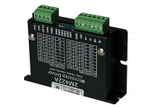
Motor Driver For Nema 2M423A 1 Pieces / (Min. Order)
-
Three Phase Motor Driver MD-3008B 1 Pieces / (Min. Order)
-
1500W Servo Motor Driver 1 Pieces / (Min. Order)
-
2000W Servo Motor Drivers 1 Pieces / (Min. Order)
-
Servo Motor Drives 1 Pieces / (Min. Order)
-
Color 3D Printer 1 Pieces / (Min. Order)
-
Motor-driven Head 1 Pieces / (Min. Order)
-
Motor Driver FH-62D 1 Pieces / (Min. Order)
-
Motor Driver FH-202F 1 Pieces / (Min. Order)
-
Motor Driver FH-82H 1 Pieces / (Min. Order)
-
Motor Driver FH-21106V 1 Pieces / (Min. Order)
-
Motor Driver FH-206V 1 Pieces / (Min. Order)
-
Motor Driver FH-115D 1 Pieces / (Min. Order)
-
Motor Driver SH-56T 1 Pieces / (Min. Order)
-
Motor Driver SH-98T 1 Pieces / (Min. Order)
-
Motor Driver DZ-188S 1 Pieces / (Min. Order)
-
Motor Driver LP-108H 1 Pieces / (Min. Order)
 Favorites
-
2000W Servo Motor Drivers
1 Pieces / (Min. Order)
-
1500W Servo Motor Driver
1 Pieces / (Min. Order)
-
 Driver Stepper Motor 2H606T
1 Pieces / (Min. Order)
Driver Stepper Motor 2H606T
1 Pieces / (Min. Order)
-
Three Phase Motor Driver MD-3008B
1 Pieces / (Min. Order)
-
 Nema 52 Stepper Motor Driver 3008A
1 Pieces / (Min. Order)
Nema 52 Stepper Motor Driver 3008A
1 Pieces / (Min. Order)
-
 Low Voltage Motor Driver 3DM683
1 Pieces / (Min. Order)
Low Voltage Motor Driver 3DM683
1 Pieces / (Min. Order)
-
Motor Driver For Nema 2M423A
1 Pieces / (Min. Order)
-
 Small Stepper Motor Driver 2M422A
1 Pieces / (Min. Order)
Small Stepper Motor Driver 2M422A
1 Pieces / (Min. Order)
-
220V Motor Driver 2H2208T
1 Pieces / (Min. Order)
-
Motor Driver 2H1106T
1 Pieces / (Min. Order)
-
 AC Stepper Motor Driver 2H8006T
1 Pieces / (Min. Order)
AC Stepper Motor Driver 2H8006T
1 Pieces / (Min. Order)
-
 1.2 Degree Nema 52 Stepper Motor 1303P
1 Pieces / (Min. Order)
1.2 Degree Nema 52 Stepper Motor 1303P
1 Pieces / (Min. Order)
-
 1.8 Degree Nema 52 Stepper Motor 130STH
1 Pieces / (Min. Order)
1.8 Degree Nema 52 Stepper Motor 130STH
1 Pieces / (Min. Order)
-
 Nema 42 Stepper Motor Round Shape 1103P
1 Pieces / (Min. Order)
Nema 42 Stepper Motor Round Shape 1103P
1 Pieces / (Min. Order)
 Frequent updates ensuring high quality data
 Over 5000 customers trust us to help grow their business!


 Menu
Menu