 Menu
Menu


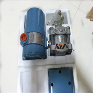
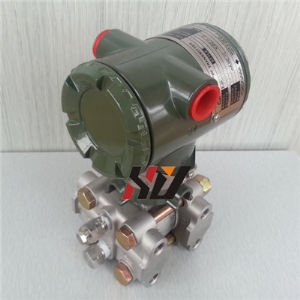
Rosemount 1151 Pressure Transmitter
-
Min Order
1
-
Product Unit
Pieces
-
Origin
China Mainland
-
Payment


- Contact Now Start Order
- Favorites Share
- Description
Product Detail
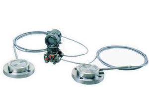
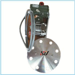
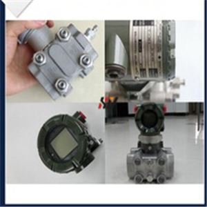
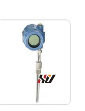
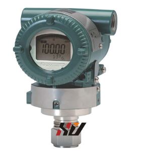
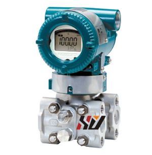
Rosemount 1151 pressure transmitter
Feature :
Power Supply The DC power supply should provide power with less than 2% ripple. The total load is the sum of the resistance of the signal leads and the load resistance of the controller, indicator, and related pieces. The resistance of intrinsic safety barriers, if used, must be included. Figure 2-7 illustrates power supply load limitations for the transmitter.The signal terminals and test terminals are located in a compartment of the electronics housing that is separate from the transmitter electronics. The
nameplate on the side of the transmitter indicates the locations of both of these compartments. The upper pair of terminals are the signal terminals and the lower pair are the test terminals. The test terminals have the same 4–20mA output as the signal terminals and are only for use with the optional integral meter or for testing.
Specifications :
Analog Displays
Option Codes M1, M2, and M6 provide local indication of the transmitter
output in a variety of scaling configurations with an indicator accuracy of ±2
percent. The plug-in mounting configuration allows for simple installation and
removal of the analog displays. The meter scaling options are shown below.
M1 Linear analog display, 0–100% scale
M2 Square-root analog display, 0–100% flow scale
M6 Square-root analog display, 0– 10v scale
LCD Displays
The LCD Display Option Codes, M4 and M7–M9, provide a highly accurate
local display of the process variable. A variety of scaling configurations are
available and listed as follows:
M4 Linear LCD Display, 0 to 100%
M7 Special scale LCD Display (specify range, mode, and
engineering units)
M8 Square-root LCD Display, 0 to 100%
M9 Square-root LCD Display, 0 to 10%
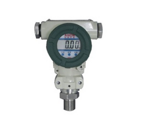
LCD Display Configuration
The Rosemount LCD Display has four digits and plugs directly into the
Rosemount 1151 Smart Pressure Transmitter to provide a highly accurate
digital display of the process variable. This manual explains the configuration
and assembly of the LCD Display and includes the applicable functional,
performance, and physical specifications. This meter adds no voltage drop in
the 4–20 mA current loop when connected directly across the transmitter test
terminals.
The LCD Display may be configured to meet specific requirements by using
the left and right calibration buttons located on the meter face as shown in
Figure 2-12. The LCD Display cannot be configured for reverse flow because
the 20 mA value must always be greater than the 4 mA value. The analog bar
graph is also shown in Figure 2-12. The 20-segment bar graph is factory
calibrated and represents 4–20 mA directly.
Teachnical parameters :


Products show :
.jpg")
.jpg")


Why chose us :


-
UNI800F Peak-holding Instrument 1 Pieces / (Min. Order)
-
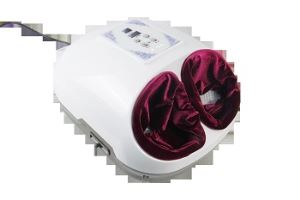
Foot Moxibustion Instrument 1 Pieces / (Min. Order)
-
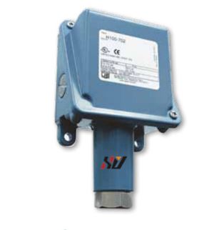
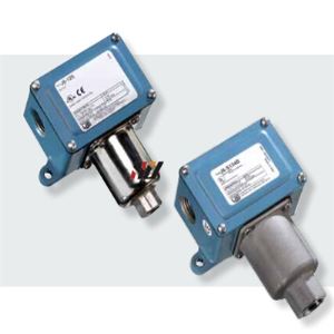
Pressure Switch 1 Pieces / (Min. Order)
-
Pressure-switch 1 Pieces / (Min. Order)

-
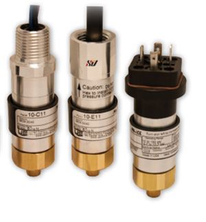
UE 10 Pressure Switch 1 Pieces / (Min. Order)
-
UE 12 Series Pressure Switch 1 Pieces / (Min. Order)
-
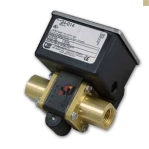
24 Series UE Pressure Switch 1 Pieces / (Min. Order)
-
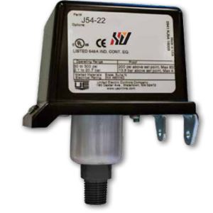
54 Series UE Pressure Switch 1 Pieces / (Min. Order)
-
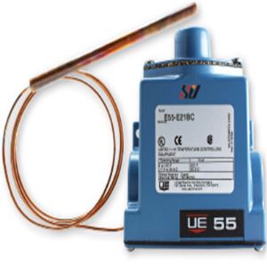
55 Series UE Temperature Switch 1 Pieces / (Min. Order)
-
UE J120 Pressure Switch 1 Pieces / (Min. Order)
-
117 Series UE Pressure Switch 1 Pieces / (Min. Order)
-
J400 UE Temperature Switch 1 Pieces / (Min. Order)
-
J6 UE Pressure And Vacuum Switches 1 Pieces / (Min. Order)
-
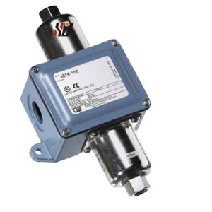
UE J21K Differential Pressure Switch 1 Pieces / (Min. Order)
-
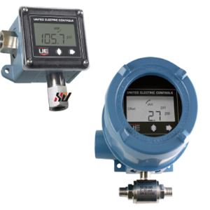
UE Temperature Transmitter With Switch 1 Pieces / (Min. Order)
-
EJA110A Differential Pressure Transmitter 1 Pieces / (Min. Order)
-
EJA118W Diaphragm SeaLED Differential Pressure Transmitters 1 Pieces / (Min. Order)
-
EJA118N Differential Pressure Transmitter 1 Pieces / (Min. Order)
-
EJA130A Differential Pressure Transmitter 1 Pieces / (Min. Order)
-
Rosemount 644 Temperature Transmitter 1 Pieces / (Min. Order)
 Favorites
-
 Rosemount 475 Hart Communicator
1 Pieces / (Min. Order)
Rosemount 475 Hart Communicator
1 Pieces / (Min. Order)
-
 Rosemount 475 Feild Communicator
1 Pieces / (Min. Order)
Rosemount 475 Feild Communicator
1 Pieces / (Min. Order)
-
 EJX510A EJX530A Absolute And Gauge Pressure Transmitter
1 Pieces / (Min. Order)
EJX510A EJX530A Absolute And Gauge Pressure Transmitter
1 Pieces / (Min. Order)
-
 EJX110A Differential Pressure Transmitter
1 Pieces / (Min. Order)
EJX110A Differential Pressure Transmitter
1 Pieces / (Min. Order)
-
Rosemount 644 Temperature Transmitter
1 Pieces / (Min. Order)
-
EJA130A Differential Pressure Transmitter
1 Pieces / (Min. Order)
-
EJA118N Differential Pressure Transmitter
1 Pieces / (Min. Order)
-
EJA118W Diaphragm SeaLED Differential Pressure Transmitters
1 Pieces / (Min. Order)
-
EJA110A Differential Pressure Transmitter
1 Pieces / (Min. Order)
-
UE Temperature Transmitter With Switch
1 Pieces / (Min. Order)
-
UE J21K Differential Pressure Switch
1 Pieces / (Min. Order)
-
J6 UE Pressure And Vacuum Switches
1 Pieces / (Min. Order)
-
J400 UE Temperature Switch
1 Pieces / (Min. Order)
-
117 Series UE Pressure Switch
1 Pieces / (Min. Order)
-
UE J120 Pressure Switch
1 Pieces / (Min. Order)
-
55 Series UE Temperature Switch
1 Pieces / (Min. Order)
-
54 Series UE Pressure Switch
1 Pieces / (Min. Order)
-
24 Series UE Pressure Switch
1 Pieces / (Min. Order)
-
UE 12 Series Pressure Switch
1 Pieces / (Min. Order)
 Frequent updates ensuring high quality data
 Over 5000 customers trust us to help grow their business!


 Menu
Menu