 Menu
Menu


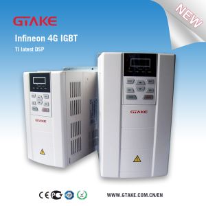
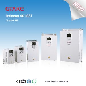
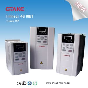
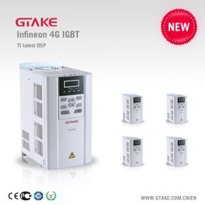
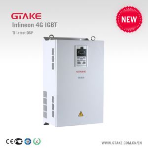
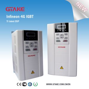
Dedicated Frequency Inverter For Water Pump (GK600-48)
-
Min Order
1
-
Product Unit
Pieces
-
Origin
China Mainland
-
Payment


- Contact Now Start Order
- Favorites Share
- Description
Product Detail
User Manual
GK600-48 Dedicated for Water Supply System
1.Instruction
GK600-48 dedicated drives are applied to constant pressure water supply system equipped a single water pump. This series have dedicated functions like pressure/frequency wakeup, timer sleep, timer sleep pressure wakeup, timer sleep pressure wakeup and sleep again, etc.
This additional manual should be used along with GK600 Series General Purpose AC Motor Drive User Manual.
Group F4, constant pressure water supply parameters, are mainly added in this user manual. Importantly PID process control should be digital setting, while feedback can be set on the basis of application.
2.Hardware Difference
No.
3.Dedicated Parameters
Param. | Designation | Range | Default | Attr. |
F4-00 | Constant pressure control | 0: Disabled 1: Enabled | 0 | × |
F4-01 | Pressure range | 0~100.00MPa | 1.00 | ? |
F4-02 | Constant pressure setting source | 0: Digital setting 1 (F4-03) 1: Digital setting 2 (F4-04) 2: AI1 3: AI2 | 0 | ? |
F4-03 | Constant pressure setting 1 | 0~100.00MPa | 0.50 | ? |
F4-04 | Constant pressure setting 2 | 0~100.00MPa | 0.50 | ? |
F4-05 | Sleep selection | 0: No sleep 1: Pressure sleep 2: Frequency sleep | 0 | ? |
F4-06 | Pressure setting at pressure sleep | 0~100.00MPa | 0.80 | ? |
F4-07 | Pressure sleep time delay | 0.0~3600.0min | 10.0 | ? |
F4-08 | Frequency setting at frequency sleep | 0.00~300.00Hz | 20.00 | ? |
F4-09 | Frequency sleep time delay | 0.0~3600.0min | 10.0 | ? |
F4-10 | Pressure wakeup in sleep | 0: Set by F4-11 1: Set by F4-12 | 0 | ? |
F4-11 | Pressure wakeup setting 1 | 0~100.00MPa | 0.30 | ? |
F4-12 | Pressure wakeup setting 2 | 0~100.00MPa | 0.30 | ? |
F4-13 | Pressure wakeup activated time | 0.0~3600.0min | 10.0 | ? |
F4-14 | Timer sleep selection | Ones place: 0: Disabled 1: Enabled Tens place: 0: No wakeup in timer sleep 1: Wakeup allowed in timer sleep | 00 | × |
F4-15 | Timer sleep start time | 0~2359 | 0 | × |
F4-16 | Timer sleep end time | 0~2359 | 0 | × |
F4-17 | Wakeup pressure in timer sleep | 0~100.00MPa | 0.10 | ? |
F4-18 | Time delay of wakeup in timer sleep | 0.0~3600.0min | 10.0 | ? |
F4-19 | Sleep-again pressure after wakeup from timer sleep | 0~100.00MPa | 0.60 | ? |
F4-20 | Sleep-again time delay after wakeup from timer sleep | 0.0~3600.0min | 10.0 | ? |
F4-20 | Sleep-again time delay after wakeup from timer sleep | 0.0~3600.0min | 10.0 | ? |
F4-21 | Maximum stop pressure | 0~100.00MPa | 1.00 | ? |
F4-22 | Upper limit pressure protection setting | 0: Disabled 1: Enabled | 0 | ? |
F4-23 | Upper limit pressure protection value | 0~100.00MPa | 0.90 | ? |
F4-24 | System clock | 0~2359 | 0 | ? |
F4-25 | Minimum stop pressure | 0~100.00MPa | 0.05 | ? |
F4-26 | Time delay of minimum stop pressure | 0.0~3600.0min | 10.0 | ? |
F4-27 | Sleep memory selection in stop | 0: Sleep status memorized in stop 1: Sleep status cleared in stop | 0 | ? |
4.Dedicated Parameters Specification
4.1F4 Group
F4 -00 | Constant pressure control | Range: 0~1 | Default: 0 |
0: Disabled
1: Enabled
Parameters in Group F4 will take effect only when this parameter is
F4 -01 | Pressure range | Range: 0~100.00MPa | Default:1.00 |
Sets the pressure range upper limit.
F4-02 | Constant pressure setting source | Range: 0~3 | Default: 0 |
0: Set by F4-03
1: Set by F4-04
2: AI1
3: AI2
Pressure setting source needs to be selected by this parameter. For water supply system and when the Group F4 are activated, F0-00 must be set to 0. The pressure determined by F4-02 selected source will be converted to a percentage value, as the dynamical PID digital setting value at F0-01.Water supply PID system setting is specified below:
1)F0-00=0 (must be)
If F4-02=0, F0-01 will be F4-03 x100.0/F4-01
If F4-02=1, F0-01 will be F4-04x100.0/F4-01
When F4-02 is set to 2 or 3, AI1 or AI2 curve will be determined by water supply pressure feedback source, and F0-01 will be a percentage value which equals to AI percentage value.
2) Set PID feedback source by F0-02.
3) Adjust PID parameters on the basis of the system's status.
F4-03 and F4-04 could be selected via the digital input terminal "constant pressure switch".
F4-03 | Constant pressure setting 1 | Range: 0~100.00MPa | Default: 0.50 |
F4-04 | Constant pressure setting 2 | Range: 0~100.00MPa | Default: 0.50 |
Constant pressure setting 1 or 2 could be switched by "constant pressure switch"terminal and F4-02 parameter value.
F4-02 value | “constant pressure switch” terminal | constant pressure setting |
0 | 0 | Digital setting 1 (F4-03) |
0 | 1 | Digital setting 2 (F4-04) |
1 | 0 | Digital setting 2 (F4-04) |
1 | 1 | Digital setting 1 (F4-03) |
F4-05 | Sleep selection | Range: 0~2 | Default: 0 |
0: No sleep
1: Pressure sleep
2: Frequency sleep
F4-06 | Pressure setting at pressure sleep | Range: 0~100.00MPa | Default: 0.80 |
F4-07 | Pressure sleep time delay | Range: 0.0~3600.0min | Default: 10.0 |
If the pressure is detected higher than F4-06 value, with time delay set by F4-07, the system immediately goes to pressure sleep mode. F4-06 and F4-07 are activated only if F4-05 is set to 1 (pressure sleep).
F4-08 | Frequency setting at frequency sleep | Range: 0.00~300.00Hz | Default: 20.00 |
F4-09 | Frequency sleep time delay | Range: 0.0~3600.0min | Default: 10.0 |
If run frequency is lower than F4-08 set value, with time delay set by F4-09, the system immediately goes to frequency sleep mode. F4-08 and F4-09 are activated only if F4-05 is set to 2 (frequency sleep).
F4-10 | Pressure wakeup in sleep | Range: 0~1 | Default: 0 |
0: set by F4-11
1: set by F4-12
F4-11 | Pressure wakeup 1 | Range: 0~100.00MPa | Default: 0.30 |
F4-12 | Pressure wakeup 2 | Range: 0~100.00MPa | Default: 0.30 |
F4-13 | Pressure wakeup activated time | Range: 0.0~3600.0min | Default: 10.0 |
Pressure wakeup 1 or 2 activated can also be determined by F4-10 and "pressure wakeup switch"terminal as below:
F4-10 value | “pressure wakeup switch” terminal | Pressure wakeup |
0 | 0 | Pressure wakeup 1 |
0 | 1 | Pressure wakeup 2 |
1 | 0 | Pressure wakeup 2 |
1 | 1 | Pressure wakeup 1 |
In sleep mode, if the feedback pressure is less than pressure wakeup setting, and maintain the time set by F4-13, the drive will immediately exit sleep mode.
F4-14 | Timer sleep selection | Range: 00~11 | Factory default: 0 |
Ones place:
0: Disabled
1: Enabled
Tens place:
0: No wakeup in timer sleep
1: Wakeup allowed in timer sleep
As long as timer sleep is enabled, pressure/frequency sleep is disabled.
F4-15 | Timer sleep start time | Range: 0~2359 | Default: 0 |
F4-16 | Timer sleep end time | Range: 0~2359 | Default: 0 |
When the time now is timer sleep start time set by F4-15, and feedback pressure is bigger than the value of F4-17, drive enters timer sleep mode immediately.
When the time now is timer sleep end time, timer sleep mode is finished.
At F4-15 and F4-16, 2359 represents time 23:59, while 1130 means 11:30.
F4-17 | Timer sleep wakeup pressure | Range: 0~100.00MPa | Default: 0.10 |
F4-18 | Timer sleep wakeup activated time | Range: 0.0~3600.0min | Default: 10.0 |
If feedback pressure is lower than the value set by F4-17, and it retains the same as long as the time set by F4-18, the drive wakes up from timer sleep mode immediately.
F4-19 | Sleep-again pressure after wakeup from timer sleep | Range: 0~100.00MPa | Default: 0.60 |
F4-20 | Sleep-again time delay after wakeup from timer sleep | Range: 0.0~3600.0min | Default: 10.0 |
If feedback pressure is higher than F4-19, and lasts the time set by F4-20, on the condition that the drive has already been woken up from timer sleep mode, the drive will get into sleep mode again.
F4-21 | Maximum stop pressure | Range: 0~100.00MPa | Default: 1.00 |
If feedback pressure is higher than the maximum stop pressure set by F4-12, the drive will stop running immediately.
F4-22 | Upper limit pressure protection setting | Range: 0~1 | Default: 0 |
0: Disabled
1: Enabled
F4-23 | Upper limit pressure protection value | Range: 0~100.00MPa | Default: 0.90 |
If upper limit pressure protection F4-22 is set to1, and while feedback pressure is higher than F4-23 set value, drive will run with lower limit frequency.
F4-24 | System clock | Range: 0~2359 | Default: 0 |
For example, 2359 means time 23:59, while 1130 means 11:30.
This parameter indicates system current time, which should be set once again every other power-up.
F4-25 | Minimum stop pressure | Range: 0~100.00MPa | Default: 0.05 |
F4-26 | Minimum stop pressure activated time | Range: 0.0~3600.0min | Default: 10.0 |
When the pressure is lower than minimum stop pressure and lasts the time set by F4-26, drive stops running. F4-25 and F4-26 are usually used for protection on the system in case of no water in the pipe network.
F4 -27 | Exit sleep mode when stop | Range: 0~1 | Default: 0 |
0: Disabled
1: Enabled
When F4-27 is set to 1, if the drive is stopped at sleep mode, the drive will exit its sleep mode. When F4-27 keeps its default setting F4-27=0, if the drive is stopped at sleep mode, the drive will maintain its sleep mode unless the pressure or frequency meets the conditions to exit sleep mode.
4.2Input terminal added parameters
C0-01 | Function of terminal X1 | 71: constant pressure switch 72: pressure wakeup switch | Default: 0 |
C0-02 | Function of terminal X2 | Default: 0 | |
C0-03 | Function of terminal X3 | Default: 0 | |
C0-04 | Function of terminal X4 | Default: 0 | |
C0-05 | Function of terminal X5 | Default: 0 | |
C0-06 | Function of terminal X6 | Default: 0 | |
C0-07 | Function of terminal X7/DI | Default: 0 | |
C0-08 | Function of terminal AI1 (Digital enabled) | Default: 0 | |
C0-09 | Function of terminal AI2 (Digital enabled) | Default: 0 | |
C0-10 | Function of terminal AI3 (Digital enabled) | Default: 0 |
4.3Output terminal added parameters
C1-00 | Function of terminal X7/DI | 34: Sleeping 35: Timer sleeping 36: Pressure-out-of-limit STOP | Default: 0 |
C1-01 | Function of terminal AI1 (Digital enabled) | Default: 0 | |
C1-02 | Function of terminal AI2 (Digital enabled) | Default: 0 | |
C1-03 | Function of terminal AI3 (Digital enabled) | Default: 0 |
4.4RUN and STOP added parameters
L1-00 | LED display 1 in RUN | Range: 0000~37FF | Default: 000F |
0: No Display; 1: Displayed
Ones place:
BIT0:Running frequency (Hz)
BIT1: Set frequency (Hz)
BIT2: Bus voltage (V)
BIT3: Output current (A)
Tens place:
BIT0: Output torque (%)
BIT1: Output power (KW)
BIT2: Output voltage (V)
BIT3: Motor speed (RPM)
Hundreds place:
BIT0: AI1 (V)
BIT1: AI2 (V)
BIT2: AI3 (V)
BIT3: Run frequency 2
Thousands place:
BIT0: DI
BIT1: External count value
BIT2: System pressure
BIT3: System time
L1-02 | LED display in STOP | Range: 0000~FF7F | Default: 000F |
Sets HMI displayed parameters in stop status. When a number of parameters are selected to be displayed, skim-through could be performed via key >> on keypad.
0: No display;
1: Displayed
Ones place:BIT0: Frequency setting (Hz)
BIT1: Bus voltage (V)
BIT2: Input terminal status
BIT3: Output terminal status
Tens place:
BIT0:AI1 (V)
BIT1:AI2 (V)
BIT2:AI3 (V)
BIT3: System time
Hundreds place:
BIT0: PID setting (%)
BIT1: PID feedback (%)
BIT2: Set length (m)
BIT3: Actual length (m)
Thousands place:
BIT0: Run linear speed (m/s)
BIT1: Set linear speed (m/s)
BIT2: External count value
BIT3: DI
Other parameters and functionalities are the same with GK600 Series General Purpose AC Motor Drives.
-
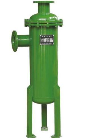
TS Series Of Compressed Air Oil Water Separator 1 Pieces / (Min. Order)
-
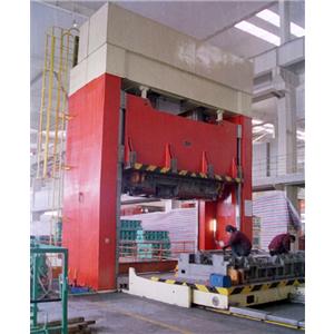
SH Series C Type Super High-Speed Press 1 Pieces / (Min. Order)
-
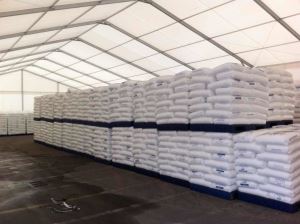
Prefab Portable Temporary Waterproof Warehouse Canopy Shelter Tent 1 Pieces / (Min. Order)
-
Fuel Injection Pump-versatile Steam Cleaner SV 1802 1 Pieces / (Min. Order)

-
HC-03 PLASMA Torch Replacement Parts 1 Pieces / (Min. Order)
-
HC-02 PLASMA Torch Replacement Parts 1 Pieces / (Min. Order)
-
HC-01 PLASMA Torch Replacement Parts 1 Pieces / (Min. Order)
-
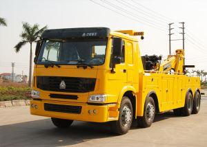
Heavy Tray Lift Wrecker Special Chassis 1 Pieces / (Min. Order)
-
Beautiful Elegant Girls Leather Watch 1 Pieces / (Min. Order)

-
High Quality Booster Cable For Car Use 1 Pieces / (Min. Order)
-
Printed Heart Shaped Gift Paper Box For Christmas 1 Pieces / (Min. Order)

-
Flat-plate Gate Valve 1 Pieces / (Min. Order)
-
HDPE Water Pipe Hard 1 Pieces / (Min. Order)

-
18650 Polymer Battery Holder Power Bank 7800mah 1 Pieces / (Min. Order)

-
18650 Polymer Battery LCD Power Bank 10400mah 1 Pieces / (Min. Order)

-
18650 Polymer Battery Aluminum Power Bank 10400mah 1 Pieces / (Min. Order)

-
18650 Polymer Battery Aluminum Power Bank 13000mah 1 Pieces / (Min. Order)

-
18650 Polymer Battery Aluminum Power Bank 20800mah 1 Pieces / (Min. Order)

-
High Quality Competitive Price Heat Transfer Vinyl For T Shirt 1 Pieces / (Min. Order)

 Favorites
-
 GK800-4T55 AC Variable Speed Drives
1 Pieces / (Min. Order)
GK800-4T55 AC Variable Speed Drives
1 Pieces / (Min. Order)
-
 GK800-4T132 Variable Speed AC Drives
1 Pieces / (Min. Order)
GK800-4T132 Variable Speed AC Drives
1 Pieces / (Min. Order)
-
 GK800-4T315 Variable Frequency Drive
1 Pieces / (Min. Order)
GK800-4T315 Variable Frequency Drive
1 Pieces / (Min. Order)
-
 GK800-2T45 VFD Drives
1 Pieces / (Min. Order)
GK800-2T45 VFD Drives
1 Pieces / (Min. Order)
-
 Variable Speed Drives For Fan
1 Pieces / (Min. Order)
Variable Speed Drives For Fan
1 Pieces / (Min. Order)
-
 GK800-4T132 Variable Speed AC Drives
1 Pieces / (Min. Order)
GK800-4T132 Variable Speed AC Drives
1 Pieces / (Min. Order)
-
 GK800-4T200 AC Drives VFD
1 Pieces / (Min. Order)
GK800-4T200 AC Drives VFD
1 Pieces / (Min. Order)
-
 GK800-4T355 Variable Speed Drives
1 Pieces / (Min. Order)
GK800-4T355 Variable Speed Drives
1 Pieces / (Min. Order)
-
 GK800-2T7.5B Big Starting Torque Variable Speed Drives
1 Pieces / (Min. Order)
GK800-2T7.5B Big Starting Torque Variable Speed Drives
1 Pieces / (Min. Order)
-
 GK600-6T Series General Purpose AC Motor Drives
1 Pieces / (Min. Order)
GK600-6T Series General Purpose AC Motor Drives
1 Pieces / (Min. Order)
-
 GK800-6T Series High Performance Vector Control VFDs
1 Pieces / (Min. Order)
GK800-6T Series High Performance Vector Control VFDs
1 Pieces / (Min. Order)
-
 GK600-4T Series General Purpose AC Motor Drives
1 Pieces / (Min. Order)
GK600-4T Series General Purpose AC Motor Drives
1 Pieces / (Min. Order)
-
 GK800-4T Series High Performance Vector Control VFDs
1 Pieces / (Min. Order)
GK800-4T Series High Performance Vector Control VFDs
1 Pieces / (Min. Order)
-
 GK600-4T Series General Purpose AC Motor Drives
1 Pieces / (Min. Order)
GK600-4T Series General Purpose AC Motor Drives
1 Pieces / (Min. Order)
-
 GK600-4T Series General Purpose AC Motor Drives
1 Pieces / (Min. Order)
GK600-4T Series General Purpose AC Motor Drives
1 Pieces / (Min. Order)
-
 GK800-4T30(B) Big Starting Torque AC Servo Drives
1 Pieces / (Min. Order)
GK800-4T30(B) Big Starting Torque AC Servo Drives
1 Pieces / (Min. Order)
-
 GK800-4T132 Variable Speed AC Drives
1 Pieces / (Min. Order)
GK800-4T132 Variable Speed AC Drives
1 Pieces / (Min. Order)
 Frequent updates ensuring high quality data
 Over 5000 customers trust us to help grow their business!


 Menu
Menu