 Menu
Menu


Brand Cell Rubber Fender Use for Marine Dock
-
Min Order
1
-
Product Unit
Pieces
-
Origin
China Mainland
-
Payment


- Contact Now Start Order
- Favorites Share
- Description
Product Detail
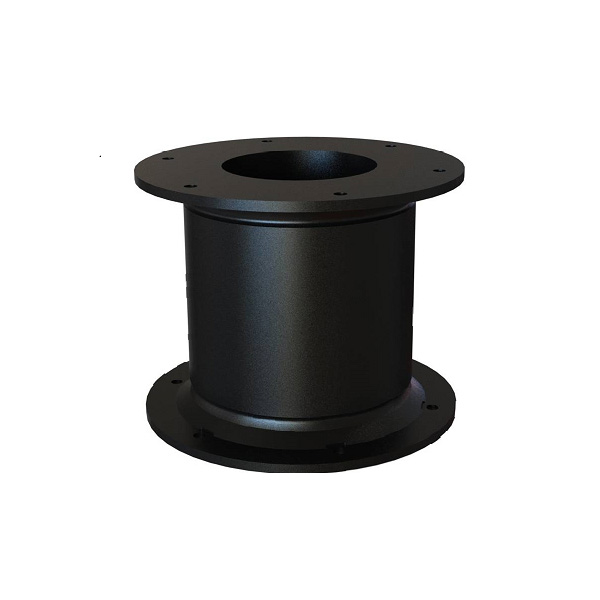
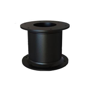
Brand Cell Rubber Fender use for marine dock
1. The advantages of super cell rubber fender
1.1 High E/R.H(energy absorption/reaction force. product height) Value
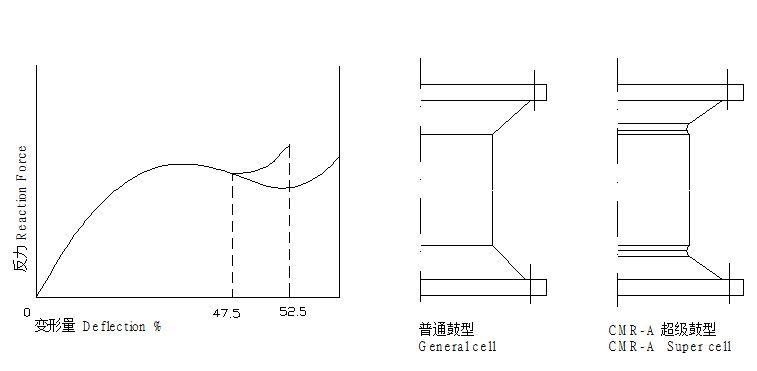
Compare with general cell rubber fenders, CMR super cell rubber fenders have 15% higher E/R.H value. The general cell rubber fender has 0.375~0.385 E/R.H, while the super one has 0.43~0.44 normally.
For Instance
Specifications | Rated Deflection% | Reaction Force | Energy Absorption KN-M | E/R.H |
CMR-A1250 | 52.5 | 696 | 382 | 0.439 |
G1250 | 47.5 | 695.5 | 333.5 | 0.384 |
CMR-A2000 | 52.5 | 1780 | 1564 | 0.439 |
G2000 | 47.5 | 1746.2 | 1334.2 | 0.382 |
1.2 More Reasonable Structure
Compare with normal rubber fender, CMR super cell rubber is more reasonable in the structure design. A smooth joint is adopted between the fender buffer and flange to reduce the stress concentration in fender bottom during the deflection, which result in more reasonable force dispersion, furthermore the deflection value of the fender is increased to 52.5% from the normal 47.5%.
1.3 Super cell rubber fender has the same installation bolt pitch and bolt holes with the general rubber fender.
1.4 Minor affection in angular berthing.
2. Specification/Dimension
Specifications(mm) | H | h | D1 | D2 | n-?d | MD | H1 | L |
CMR-A400 | 400 | 25 | 550 | 650 | 4-?30 | 22 | 10 | 270 |
CMR-A500 | 500 | 25 | 550 | 650 | 4-?32 | 24 | 12 | 300 |
CMR-A630 | 630 | 30 | 700 | 840 | 4-?39 | 30 | 14 | 330 |
CMR-A800 | 800 | 30 | 900 | 1050 | 6-?40 | 32 | 14 | 360 |
CMR-A1000 | 1000 | 35 | 1100 | 1300 | 6-?47 | 39 | 18 | 430 |
CMR-A1150 | 1150 | 40 | 1300 | 1500 | 6-?50 | 42 | 22 | 500 |
CMR-A1250 | 1250 | 45 | 1450 | 1650 | 6-?53 | 45 | 22 | 500 |
CMR-A1450 | 1450 | 47 | 1650 | 1850 | 6-?61 | 52 | 26 | 570 |
CMR-A1600 | 1600 | 50 | 1800 | 2000 | 8-?61 | 52 | 28 | 570 |
CMR-A1700 | 1700 | 55 | 1900 | 2100 | 8-?66 | 56 | 30 | 620 |
CMR-A2000 | 2000 | 55 | 2000 | 2200 | 8-?74 | 64 | 32 | 700 |
CMR-A2250 | 2250 | 60 | 2300 | 2550 | 10-?74 | 64 | 36 | 700 |
CMR-A2500 | 2500 | 70 | 2700 | 2950 | 10-?74 | 64 | 38 | 700 |
CMR-A3000 | 3000 | 75 | 3150 | 3350 | 12-?90 | 76 | 40 | 800 |
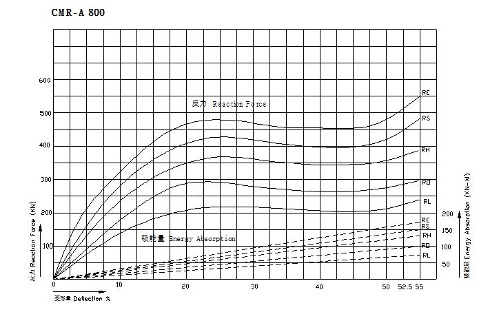
3. CMR Cell Rubber Fender Performance
Note:
(1) RE-Extreme high Reaction Force, RS-Super high Reaction Force, RH-High Reaction Force RO-Standard Reaction Force, RL-Low Reaction Force
(2)R-Reaction Force, E-Energy Absorption;
(3)Rated Deflection:52.5%, Maximum Deflection:55%
(4)Performance tolerance:±10%
4. Performance Curve
5. Installation Figure
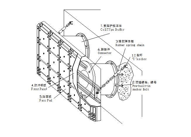
Main Accessories and Applications
NO. | Description | Applications | Material |
1 | Rubber Fender Buffer | Absorb ship impact energy to protect dock and vessels | Rubber |
2 | Pre-built-in U Anchor | Holding chains | Q235 Painted or Hot-galv. |
3 | Pre-built-in Bolt & Nut | Fasten fenders onto dock | Stainless steel,Q235 Hot-galv. |
4 | Front Panel | Reduce surface pressure in avoid of damage of the fenders or vessels | Q235 Painted |
5 | Facing Pad | Reduce friction coefficient to protect hull | UHMW-PE |
6 | Link Bolt & Nut | Connect the fender & Front panel and Face Pad | Stainless steel,Q235 Hot-galv. |
7 | Chains(Including tensile chain, weight chain & shear chain ) | 1. Limit fenders deflection while fender local part under strain | Q235 SBC490 Hot-galv. or painted |
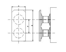
6. Structure & Specifications of Front Panel and Selection of Rubber Spring Chain
6.1 One cell one Panel (1×1) form
6.2 Two cell one Panel (2×1) in horizontal form
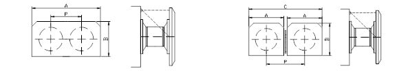
6.3 Two cell one Panel (2×1) in vertical form
7. Min. spacing between fender installation & Min. spacing between fender and concrete structure
The fender buffer part will bulge under compression, therefore a certain space must be left in fender installation in avoid of buffer contacting each other. In addition the pre-cast in bolt will generate tensile strength and shear strength upon the concrete structure due to fender deflection which will damage the concrete structure. Therefore a certain space between pre-cast in bolts and concrete structure mus t be left. | 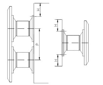 |
Specifications | CMR-A 400 | CMR-A 500 | CMR-A 630 | CMR-A 800 | CMR-A 1000 | CMR-A 1150 | CMR-A 1250 | CMR-A 1450 | CMR-A 1600 | CMR-A 1700 | CMR-A 2000 | CMR-A 2250 | CMR-A 2500 | CMR-A 3000 |
H | 180 | 185 | 210 | 230 | 255 | 280 | 290 | 350 | 350 | 380 | 430 | 430 | 450 | 510 |
P | 700 | 700 | 880 | 1120 | 1500 | 1730 | 1870 | 2180 | 2400 | 2550 | 2880 | 3360 | 3730 | 4500 |
8. Installation Notice
When assembling fender system onto the dock wall, the following points should be noted.
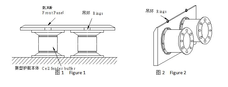
8.1 The difference of front panel between upper and lower parts.
There are rings on the top or back of the front panel for the panel to be hung with. The rings should be kept upward while installation, as shown in figure 1 and figure 2.
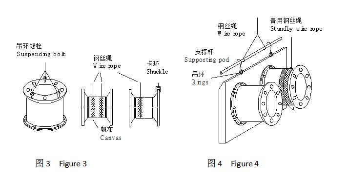
8.2 Fender Suspending Methods
(1)The suspending way of single fender, as (2) The suspending way of compound fender with
shown in figure3. front panel, as shown in figure4.
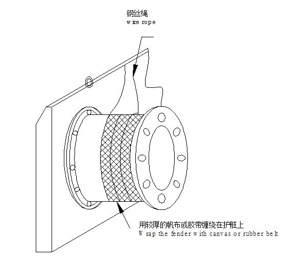
8.3 When install fender onto the pier wall
The fender buffer and the front panel should be tightened closely, when the bolt holes position of the buffer need to be adjusted following the base angle, the factors specified below need to be considered.
(1) Dislocation on circumference
Wrap the wire rope double-stranded on the buffer(as shown in figure 5) for adjustment.
(2) Dislocation of high, low, left and right orientation.
Loose the fastening boles at the front panel.
Align to foot location and then fasten. The bolts should be tightened enough during fastening (Shown in figure
5).
-
Rubber Grommet Mould 1 Pieces / (Min. Order)
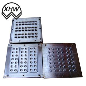
-
Rubber Grommet 1 Pieces / (Min. Order)
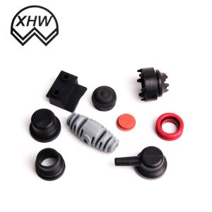
-
TPE Material Cementing ABS Wheel 1 Pieces / (Min. Order)
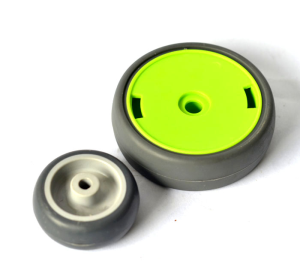
-
TPE Material Charger Case 1 Pieces / (Min. Order)
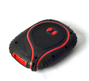
-
TPE Material Adult Supplies 1 Pieces / (Min. Order)
-
TPE Plastic Cutting Board 1 Pieces / (Min. Order)
-
TPE Special Materials For MI LED Light 1 Pieces / (Min. Order)
-
TPE Material Adult Products 1 Pieces / (Min. Order)
-
TPE Adult Sex Toys 1 Pieces / (Min. Order)
-
TPE Material Fruit Basket 1 Pieces / (Min. Order)
-
TPE Material Bicycle Pedal 1 Pieces / (Min. Order)
-
TPE Material Food Seal Cover 1 Pieces / (Min. Order)
-
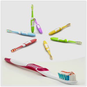
TPE Material Toothbrush 1 Pieces / (Min. Order)
-
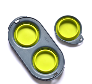
TPE Material Dog Bowl 1 Pieces / (Min. Order)
-
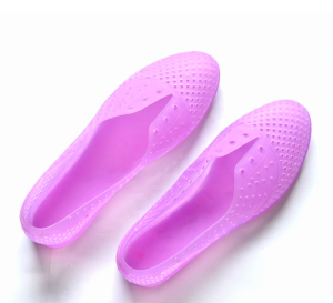
TPE Materail Plastic Shoes 1 Pieces / (Min. Order)
-
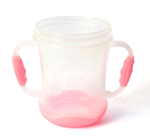
TPE Material Baby Cup 1 Pieces / (Min. Order)
-
TPE Material Sports Bottle 1 Pieces / (Min. Order)
-
TPE Material Wire 1 Pieces / (Min. Order)
-
TPE Material Shower 1 Pieces / (Min. Order)
-
TPE Material Pipe 1 Pieces / (Min. Order)
 Favorites
-
 Professional Workshop Steel Structure
1 Pieces / (Min. Order)
Professional Workshop Steel Structure
1 Pieces / (Min. Order)
-
 High Quality Different Kind Steel Tower for Various Use
1 Pieces / (Min. Order)
High Quality Different Kind Steel Tower for Various Use
1 Pieces / (Min. Order)
-
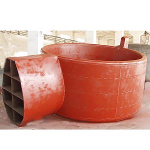 Professional Various Brand Ship Outfitting
1 Pieces / (Min. Order)
Professional Various Brand Ship Outfitting
1 Pieces / (Min. Order)
-
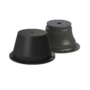 Cone Rubber Fender with High Quality and Performance
1 Pieces / (Min. Order)
Cone Rubber Fender with High Quality and Performance
1 Pieces / (Min. Order)
 Frequent updates ensuring high quality data
 Over 5000 customers trust us to help grow their business!


 Menu
Menu